Vascular interventional surgical robot
A technology of interventional surgery and robotics, applied in the direction of surgical robots, etc., can solve problems such as complex operations, high risks, and restrictions on wide application
- Summary
- Abstract
- Description
- Claims
- Application Information
AI Technical Summary
Problems solved by technology
Method used
Image
Examples
Embodiment 1
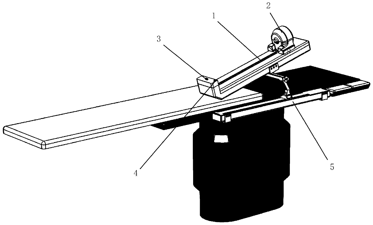
[0031] combine figure 1 Explain the installation position of each module of the vascular interventional surgery robot: the delivery device of the interventional surgery robot is composed of 1. a propulsion device, 2. a twisting device, 3. a guide wire guiding device, 4. a wire pressing device and 5. a bedside positioning device. The twisting device is installed on the sliding table of the propulsion device, the guide wire guide device is installed at the front end of the sliding guide rail of the propulsion device at the same height as the twisting device, and the wire pressing device is located on the side at the same height as the guide wire guiding device and the twisting device. One end of the bedside positioning device is connected to the working part of the surgical robot and the other end is connected to the side of the operating table. Through the coordinated action of each functional module, the guide wire catheter can be effectively implemented to intervene in blood ...
Embodiment 2
[0033] Embodiment 2 is on the basis of Embodiment 1, combining figure 2Explain the structure of the propulsion device: the driving motor 1-9 rotates forward, drives the coupling 1-3 to rotate, the coupling 1-3 drives the ball screw 1-1 to rotate, and the screw 1-1 rotates to drive the screw nut and slide The block 1-5 and the sliding table 1-8 move forward to realize the action of pushing the guide wire. The sliding table 1-8 is installed on the sliding block 1-5 through screw connection, and the sliding block 1-5 cooperates with the linear guide rail 1-2. , to ensure that the sliding table 1-8 moves along a straight line; the driving motor 1-9 reverses, and the sliding table 1-8 moves backward to realize the action of pulling back the guide wire. The propulsion device uses a stepping motor to drive the rotation of the ball screw to drive the movement of the slide table, and uses a linear guide rail for circumferential limit and axial guidance, which can realize the accurate ...
Embodiment 3
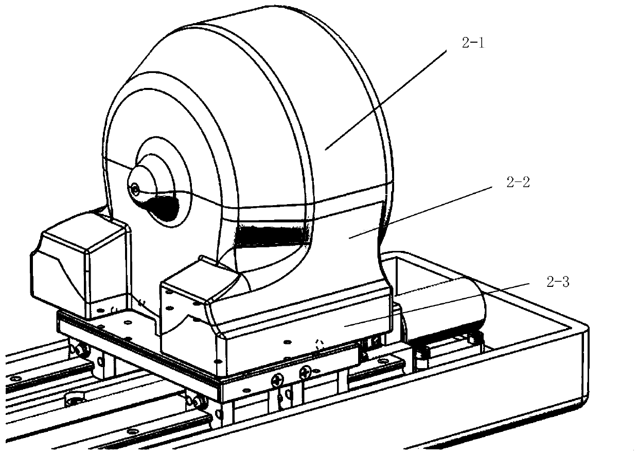
[0035] Embodiment 3 is on the basis of embodiment 2, image 3 and Figure 4 The installation position and external structure of the twisting device are illustrated: the twisting device 2 is connected with the sliding table 1-8 of the propulsion device, and the connecting base is installed on the sliding table 1-8 using long bolts, and the casing 2-1 and the The lower packaging shells 2-2 are all plastic structures connected by bayonet sockets. The twisting device 2 is installed on the slide table 1-8 and can move back and forth synchronously with the propulsion device in space.
PUM
 Abstract
Description
Claims
Application Information
 - Generate Ideas
- Intellectual Property
- Life Sciences
- Materials
- Tech Scout
- Unparalleled Data Quality
- Higher Quality Content
- 60% Fewer Hallucinations
Browse by: Latest US Patents, China's latest patents, Technical Efficacy Thesaurus, Application Domain, Technology Topic, Popular Technical Reports.
© 2025 PatSnap. All rights reserved.Legal|Privacy policy|Modern Slavery Act Transparency Statement|Sitemap|About US| Contact US: help@patsnap.com


