Multi-phase voltage stabilizer for phase current testing in slope current mode
A technology of ramp current and phase current, which is applied in the direction of instruments, regulating electrical variables, control/regulation systems, etc., and can solve problems such as unavailable and complex fault protection
- Summary
- Abstract
- Description
- Claims
- Application Information
AI Technical Summary
Problems solved by technology
Method used
Image
Examples
Embodiment 1
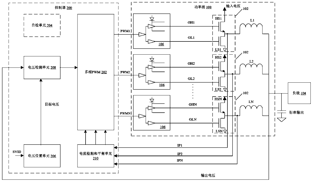
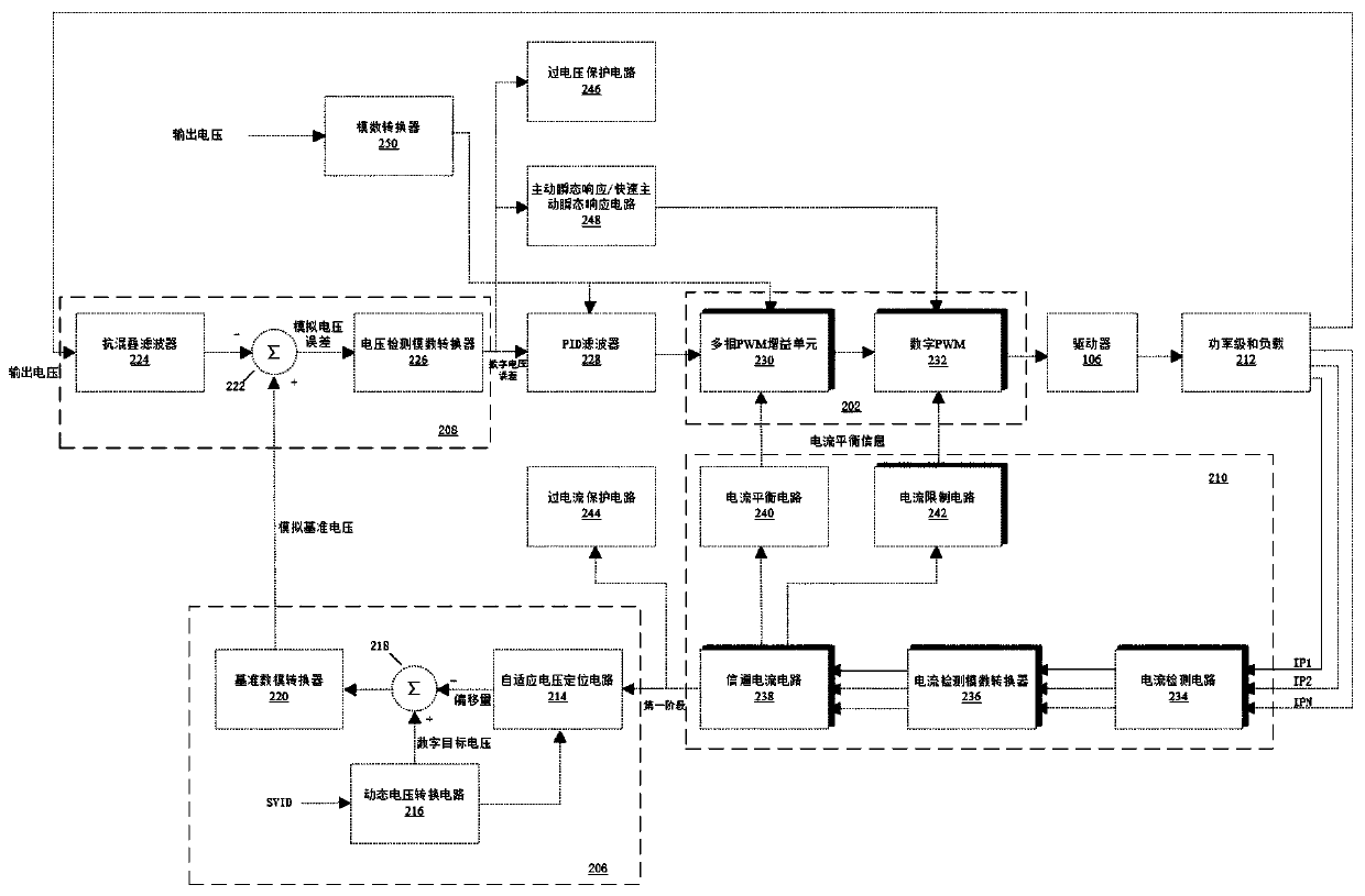
[0044] Embodiment One: The self-test unit 204 includes a ripple current fault monitor 410 that analyzes the input to the current balancing circuit 240, as indicated by the single dashed line leading to the ripple current fault monitor 410, at During normal operation of a multi-phase switching regulator, the phase current should increase or decrease depending on the state of the power switch, and the output phase 102 in normal operation will always have some ripple current, due to the synchronous switching characteristics of the regulator, the ripple current The ripple current pattern is well known and easily identifiable in the current sense waveform, the ripple current can change from DCM to CCM, so the ripple current fault monitor 410 should be aware of the mode of operation, there is no way to detect the expected ripple current pattern and the expected Amplitude current ripple can be caused by bad driver 106, output stage transistors, inductors, or current sense network 234....
Embodiment 2
[0045]Embodiment two: the self-test unit 204 includes a ramp current fault monitor 420, and the ramp current fault monitor 420 analyzes the output of the dynamic voltage conversion circuit (DVID) 216 and the channel current circuit 238, which is led to the ramp current fault monitor 420 The two dashed lines indicate that the start-up of a multiphase regulator can be used to determine a typical profile of the start-up ramp current, e.g., with a desired upper and lower limit depending on the start-up rate and total output capacitance, and a voltage range at which In the range where the load 104 is not expected to turn on, for example, the operating voltage of the integrated circuit is minimal, the ramp current fault monitor 420 checks the start-up ramp to Determine if the current is within the expected range. Changes in current distribution can indicate problems such as bad driver 106, output phase transistors, inductors, current sense network 234, or leaky output capacitors. Ram...
Embodiment 3
[0046] Embodiment three; self-test unit 204 includes phase sequence fault monitor 430, and phase sequence fault monitor 430 analyzes the output of phase current (IP1, IP2, ..., IPN) and dynamic voltage conversion circuit (DVID), such as leading to phase Represented by the four dashed lines of sequence fault monitor 430, the multiphase regulator can operate in single-phase mode, wherein only one output phase 102 is active and regulates the output, and phase sequence fault monitor 430 controls one or more output phases 102 at a time. Sequenced to test whether each output phase 102 is functioning properly, thereby ensuring that each output phase 102 is functioning properly, the phase sequence fault monitor 430 determines whether the corresponding monitored phase current responds in a predetermined (expected) manner, according to one embodiment, Phase Sequence Fault Monitor 430 monitors phase currents and output voltages (Vsense) during the sequencing of output phases 102, for exam...
PUM
 Abstract
Description
Claims
Application Information
 - R&D
- Intellectual Property
- Life Sciences
- Materials
- Tech Scout
- Unparalleled Data Quality
- Higher Quality Content
- 60% Fewer Hallucinations
Browse by: Latest US Patents, China's latest patents, Technical Efficacy Thesaurus, Application Domain, Technology Topic, Popular Technical Reports.
© 2025 PatSnap. All rights reserved.Legal|Privacy policy|Modern Slavery Act Transparency Statement|Sitemap|About US| Contact US: help@patsnap.com


