Bearing retainer rotating speed measuring system
A bearing cage and measurement system technology, which is applied in the field of bearing cage speed measurement system, can solve the problems of not adapting to high temperature oil mist environment conditions, low measurement accuracy, high cost, etc., to achieve controllable residual magnetism, high test accuracy, The effect of low energy consumption
- Summary
- Abstract
- Description
- Claims
- Application Information
AI Technical Summary
Problems solved by technology
Method used
Image
Examples
Embodiment 1
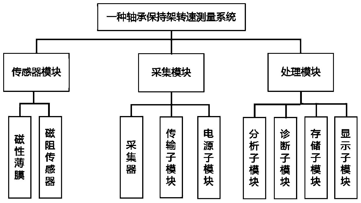
[0044] Example 1, see figure 1 As shown, a bearing cage rotation speed measurement system includes: a sensor module, including a magnetic film fixed on the end face of the cage and a magnetoresistive sensor for receiving magnetic signals; an acquisition module for collecting magnetic information received by the magnetoresistive sensor and transmitted to the signal processing module; the processing module is used to perform time-frequency analysis on the magnetic signal to calculate the amplitude and frequency of the magnetic data signal, obtain the frequency domain waveform diagram of the magnetic data signal, and obtain the cage through waveform analysis and calculation speed.
[0045] Specifically, the magnetoresistive sensor is a TMR tunnel magnetoresistive sensor, which uses the quantum tunneling effect to realize the reading of the "encoded" information of the magnetic film. The TMR tunnel magnetoresistive sensor 4 has the characteristics of small size and high precision...
Embodiment 2
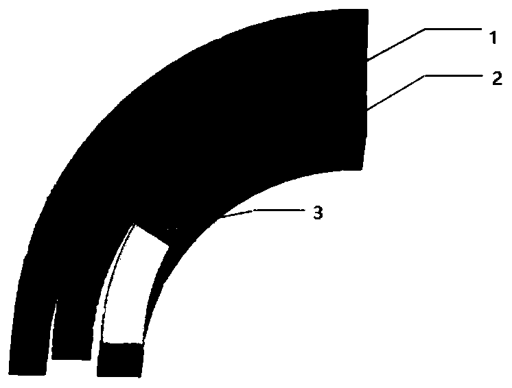
[0049] Example 2, see figure 2 Shown is the schematic diagram of the cross section of the cage of the present invention, the magnetic film 2 is installed on the cage 1, the TMR tunnel magnetoresistive sensor probe 3 is vertically arranged with the magnetic film 2, and the magnetic film with a thickness of one layer of micron on the end face of the cage 1, the magnetic film Magnetically encoded information with N pole and S pole arrangement.
[0050] Specifically, the arrangement method of the magnetically encoded information is that N poles and S poles are arranged alternately or magnetic poles are arranged in the same direction.
[0051] It is worth noting that when the arrangement method of the magnetic encoding information is alternate arrangement of N poles and S poles, the end face of the cage is covered with magnetic film collectors to obtain regular waveforms. When the magnetic poles are arranged in the same direction, the distance between the magnetic poles is kept a...
Embodiment 3
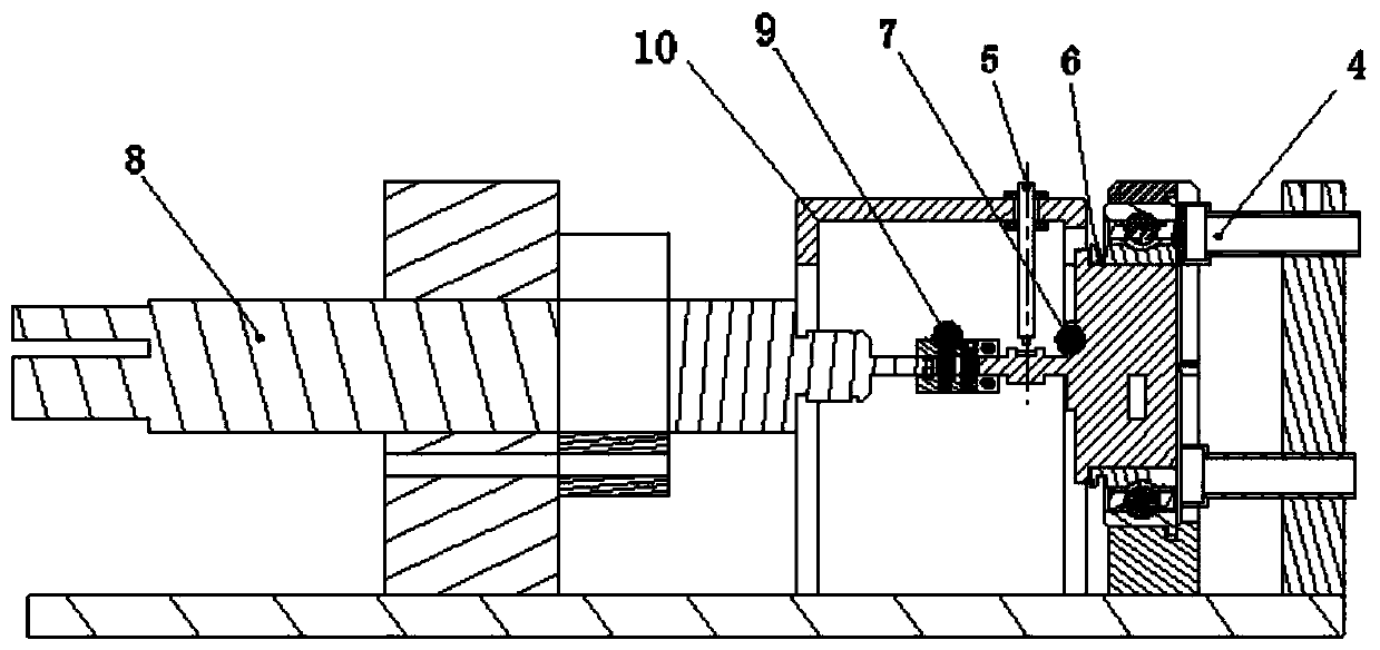
[0056] Example 3, see image 3 In the rotational speed measurement system shown, two TMR tunnel magneto-resistance sensors 4 are arranged on one side of the bearing 6, and the TMR tunnel magneto-resistance sensors 4 are arranged perpendicular to the end face of the bearing cage, and are kept 1 mm to 5 mm away from the magnetic film 2 on the cage The left and right spacing, the shaft 7 protruding from the other side of the bearing 6 is connected to the high-speed motor 8 through the coupling 9, and a protective cover 10 for protecting the coupling is provided between the bearing 6 and the high-speed motor 8, and the eddy current sensor 5 is installed in the protective cover 10, the eddy current sensor 5 is arranged perpendicular to the axis 7, and keeps a distance from the axis 7 within about 1 mm. When the motor 8 drives the bearing 6 to rotate, the TMR tunnel magnetoresistive sensor 4 collects the magnetic signal on the cage to calculate the cage speed, the eddy current senso...
PUM
| Property | Measurement | Unit |
|---|---|---|
| Thickness | aaaaa | aaaaa |
Abstract
Description
Claims
Application Information
 - R&D Engineer
- R&D Manager
- IP Professional
- Industry Leading Data Capabilities
- Powerful AI technology
- Patent DNA Extraction
Browse by: Latest US Patents, China's latest patents, Technical Efficacy Thesaurus, Application Domain, Technology Topic, Popular Technical Reports.
© 2024 PatSnap. All rights reserved.Legal|Privacy policy|Modern Slavery Act Transparency Statement|Sitemap|About US| Contact US: help@patsnap.com


