
Amplitude and phase test system of active phased-array radar T/R assemblies

A phased array radar, amplitude and phase testing technology, applied to radio wave measurement systems, instruments, etc., can solve the problems of reducing the reliability and stability of the test system, increasing the frequency of use of the switch matrix, and affecting the test results, etc., to achieve The effect of high test reliability, high test efficiency and simple circuit

Active Publication Date: 2016-01-20
LINGBAYI ELECTRONICS GRP
View PDF5 Cites 43 Cited by
  • Summary
  • Abstract
  • Description
  • Claims
  • Application Information

AI Technical Summary

Problems solved by technology

On the whole, this method has the following disadvantages: First, whether it is T branch or R branch test, each test can only be carried out on one T / R component, not only the coupled test response range is small, and it is susceptible to noise interference, Affects the measurement accuracy, and the test efficiency is low, especially for large-scale active phased array radar, due to the large number of T / R components, the restriction on test efficiency is more obvious
Secondly, the greater the number of T / R components, the larger the switch matrix required, and each test can only be performed on one T / R component, which greatly increases the frequency of use of the switch matrix, which will reduce the test System Reliability and Stability
In addition, each test can only allow one T / R component under test to work normally, and other T / R components must be turned off. If some T / R components fail and cannot be turned off during the test, it is likely to seriously affect the test results of the current test

Method used


Image

  • Amplitude and phase test system of active phased-array radar T/R assemblies
  • Amplitude and phase test system of active phased-array radar T/R assemblies
  • Amplitude and phase test system of active phased-array radar T/R assemblies

Examples


Embodiment Construction

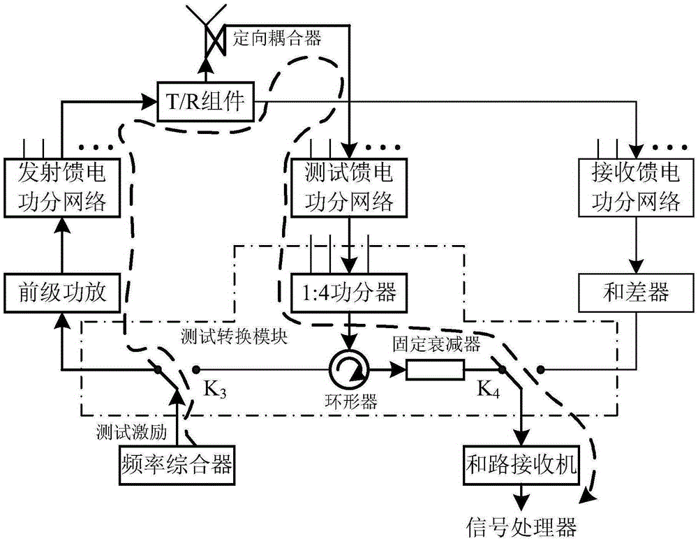
[0019] refer to figure 1. In the implementation case described below, the active phased array radar T / R component amplitude and phase test system consists of a test conversion module, an antenna directional coupler, a test feed power distribution network and a frequency synthesizer, a wave controller, and a preamplifier , Transmitting and receiving feed power distribution network, T / R components, summer, sum receiver, signal processor, terminal and other extensions. Except that the first three components are new hardware overheads, the other extensions basically reuse the hardware system of the radar under test when it works normally. Among them, the directional coupler is integrated in each radar antenna unit, which can realize the multiplexing of the test feed power sub-network during the T test and the R test, that is, in the T test mode, it is used to transfer the output signal of the T branch of each T / R component Coupled to the test feed power distribution network; in ...


PUM


Abstract

The invention provides an amplitude and phase test system of active phased-array radar T / R assemblies, and aims at providing the amplitude and phase test system of high efficiency, reliability and test precision. The N T / R assemblies are connected to antenna directional couplers via two paths of test feed power dividing networks respectively; a frequency synthesizer, a pre-stage power amplifier, a sum and difference device, a sum circuit receiver and a test conversion module are connected between the test feed power dividing networks at the front and tail ends respectively; when test starts, a terminal in the emission T test or reception R test mode emits a test instruction to the frequency synthesizer, the frequency synthesizer outputs test start and test pulse signals, and identical test excitation signals are generated in each beat according to the test pulse; and a wave controller controls different paths of phase shifters on the basis of an orthogonal coding rule, orthogonal phase modules is carried out on the test excitation signals respectively, the modulated signals are input to a signal processor, and amplitude and phase test for all the T / R assemblies is completed.

Description

technical field [0001] The invention relates to an active phased array radar T / R assembly amplitude and phase testing system. Background technique [0002] In modern radar technology, active phased array radar occupies a very important position, and it is widely used in civil and national defense fields. With the continuous development of high-power solid-state power devices and monolithic microwave integrated circuits, solid-state T / R components can be installed in each phased array radar antenna unit channel to become an active phased array radar antenna. Compared with conventional radar, active phased array radar has many advantages such as long detection distance, strong anti-interference ability, no inertial beam scanning, high reliability, strong maintainability, programmable beamforming and discrete aperture power space synthesis. , has incomparable advantages over traditional mechanical scanning radars in terms of power-aperture product, anti-jamming, multi-target t...

Claims


Application Information

Patent Timeline
Patent Type & Authority Applications(China)
IPC IPC(8): G01S7/40
CPCG01S7/40
Inventor 刘华林李海彬王用王山川周强延伟勤张静
Owner LINGBAYI ELECTRONICS GRP
Learn More