
In-situ high-frequency fatigue material mechanical test platform under scanning electron microscope based on stretching/compressing mode

A test platform and scanning electron microscope technology, applied in the electromechanical field, can solve the problems of lack of macro-scale cross-scale in-situ nanomechanical testing, limiting research depth and development, and expensive fatigue testing machines, etc., to achieve good application and development prospects, good Structural compatibility, testing content-rich effects

Active Publication Date: 2012-01-25
JILIN UNIV
View PDF5 Cites 45 Cited by
  • Summary
  • Abstract
  • Description
  • Claims
  • Application Information

AI Technical Summary

Problems solved by technology

[0005] At present, the research on in-situ fatigue testing related instruments that can be used under the scanning electron microscope is still in its infancy, specifically as follows: (1) From the perspective of testing means and methods, the ex-situ testing is mainly carried out with the help of commercial fatigue testing machines. Fatigue testing, and the fatigue testing machine is expensive, the working noise is loud, the debugging is complicated, the test content is single, and there is little mention of the in-situ fatigue testing device based on the tension mode with a compact structure and a small size
(2) Due to the limitation of the cavity space of the scanning electron microscope, most of the current methods are focused on the simple in-situ nanometer test of extremely small structures such as nanometer and thin film materials based on the micro / nanoelectromechanical system technology, and lack of macroscopic measurements. Cross-scale in-situ nanomechanical testing of dimensions (thin film materials or three-dimensional specimens), due to the existence of size effects, the research on micro-components restricts the evaluation of the mechanical properties of larger-scale components; (3) from the perspective of test frequency , the current in-situ fatigue testing machines generally can only provide low-cycle fatigue testing below 50Hz, which does not match the actual working conditions of materials and their products, and also limits the in-depth and development of related research

Method used


Image

  • In-situ high-frequency fatigue material mechanical test platform under scanning electron microscope based on stretching/compressing mode
  • In-situ high-frequency fatigue material mechanical test platform under scanning electron microscope based on stretching/compressing mode
  • In-situ high-frequency fatigue material mechanical test platform under scanning electron microscope based on stretching/compressing mode

Examples


Embodiment Construction

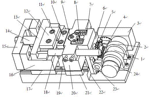
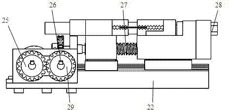
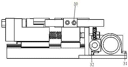
[0029] The detailed content of the present invention and its specific implementation will be further described below in conjunction with the accompanying drawings.

[0030] see Figure 1 to Figure 8 , the in-situ high-frequency fatigue material mechanics testing platform under the scanning electron microscope based on the tension / compression mode of the present invention includes a precision loading unit, a precision motion conversion unit, a load / displacement signal acquisition and control unit, a high-frequency drive unit and a test piece Clamping and connecting unit;

[0031] The precision loading unit is: the DC servo motor 1 is connected to the test platform base 22 through the motor flange frame 2 , Provide a given angular velocity and dynamic torque output through precise pulse / direction control; the DC servo motor 1 is fixed on the test platform base 22 through the motor flange fixing screw 31;

[0032] The precision motion conversion unit is: a first-stage spur gear...


PUM

PropertyMeasurementUnit
lengthaaaaaaaaaa

Abstract

The invention relates to an in-situ high-frequency fatigue material mechanical test platform under a scanning electron microscope based on a stretching / compressing mode and belongs to the field of machinery and electronics. The test platform comprises a precise loading unit, a precise motion conversion unit, a load / displacement signal acquisition and control unit, a high-frequency driving unit and a test piece clamping and connecting unit. The test platform provided by the invention has the advantages that the structure is compact, the test precision is high, the strain rate and the test frequency are controllable, an in-situ high-frequency test based on the stretching / compressing mode can be performed on a three-dimensional test piece aiming at centimeter-scale or above in characteristicdimension under the condition of observation of various imaging instruments, the on-line monitoring can be carried out on the microcosmic deformation, damage and breaking process of a material under a fatigue stress, and a novel test method for revealing microcosmic deformation behaviors and a damage system of the material is provided.

Description

technical field [0001] The invention relates to electromechanical products, in particular to an in-situ high-frequency fatigue material mechanics testing platform under a scanning electron microscope based on a tension / compression mode. It has good compatibility with scanning electron microscopes, atomic force microscopes, Raman spectrometers and optical microscopes. Combined with the above-mentioned imaging instruments, the microscopic deformation, damage and On-line observation of the damage process can realize the collection, recording and control of load / displacement signals, and provides a test method for revealing the mechanical properties and damage mechanism of materials at the micro-nano scale. Background technique [0002] In-situ micro-nano mechanical testing technology refers to the process of testing the mechanical properties of specimen materials at the micro-nano scale, through imaging instruments such as electron microscopes, atomic force microscopes, or op...

Claims


Application Information

Patent Timeline
Patent Type & Authority Applications(China)
IPC IPC(8): G01N3/08G01N3/02
Inventor 赵宏伟马志超李秦超王开厅胡晓利黄虎
Owner JILIN UNIV
Learn More