
Silicon carbide fiber heat treatment roller bed furnace

A silicon carbide fiber, roller furnace technology, applied in furnaces, furnace types, lighting and heating equipment, etc., can solve the problems of dust generation, uneven temperature, time-consuming work, etc., to save energy and improve production efficiency.

Active Publication Date: 2020-08-25
48TH RES INST OF CHINA ELECTRONICS TECH GROUP CORP +1
View PDF5 Cites 0 Cited by
  • Summary
  • Abstract
  • Description
  • Claims
  • Application Information

AI Technical Summary

Problems solved by technology

The hearth of the existing roller furnace is generally built with refractory materials. The refractory materials are generally light or heavy insulation bricks, ceramic fiber boards, etc. During use, dust will be generated, or tiny particles of bricks will fall, which will affect the box. The cleanliness of the material in the bowl cannot meet the requirements of the polycarbosilane (PCS) fiber treatment process for the production environment
In addition, the existing roller furnace generally adopts a single independent heating element arranged at a certain distance on the upper and lower sides of the furnace. The temperature at the sagger in the furnace is uneven, and in the production process of silicon carbide fiber, the continuous production of the intermediate product polycarbosilane (PCS) fiber non-melting treatment process and thermal cross-linking treatment process requires very high process parameters. The maximum use temperature of non-melting treatment is about 250°C, and the maximum use temperature of thermal crosslinking treatment is about 500°C. Under such low temperature conditions, it is very difficult to achieve temperature uniformity at the sagger in the furnace to ±5°C
Furthermore, in order to improve the temperature uniformity in the furnace of the equipment, the spacing between the heating elements is usually designed to be small, resulting in an increase in the number of elements. When the number of elements is large, it is necessary to install and replace each heating element one by one. more time-consuming

Method used


Image

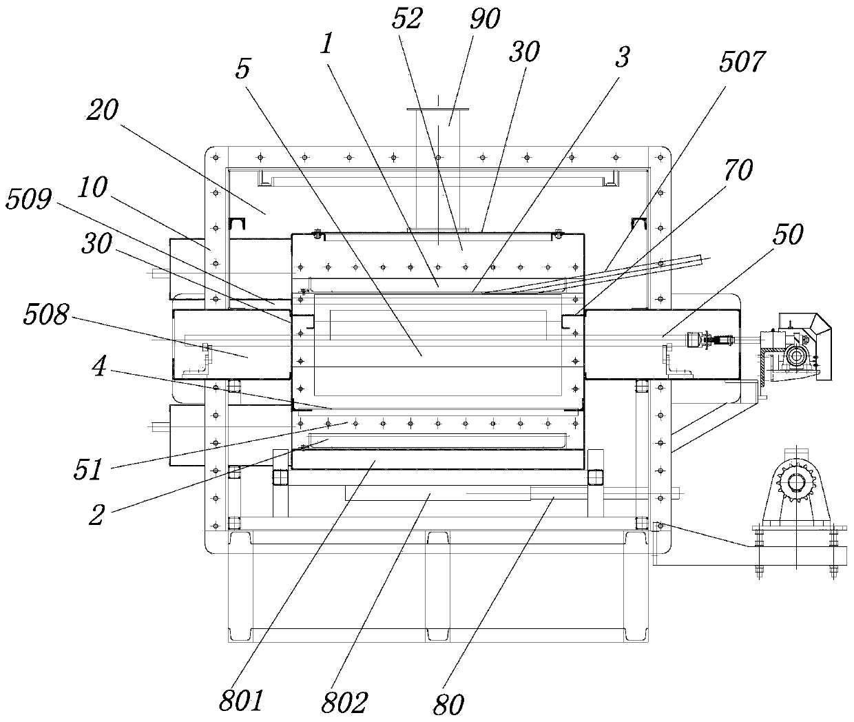
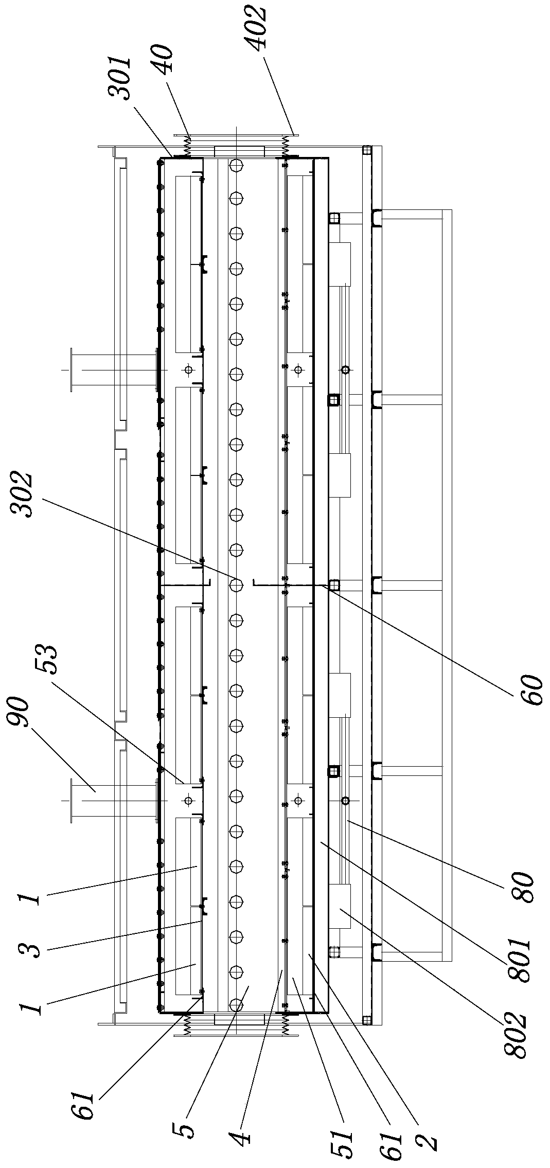
  • Silicon carbide fiber heat treatment roller bed furnace
  • Silicon carbide fiber heat treatment roller bed furnace
  • Silicon carbide fiber heat treatment roller bed furnace

Examples


Embodiment Construction

[0030] The present invention will be described in further detail below in conjunction with the accompanying drawings and specific embodiments.

[0031] Figure 1 to Figure 12An embodiment of the roller furnace for heat treatment of silicon carbide fibers of the present invention is shown. The roller furnace for heat treatment of silicon carbide fibers in this embodiment includes a conveying roller table 50 and a feeding roller table 100 arranged at one end of the conveying roller table 50 , and the blanking roller table 200 located at the other end of the conveying roller table 50, the conveying roller table 50 is sequentially provided with a first cleaning transition chamber 501, a non-melting section furnace body 504, and a second cleaning transition chamber from the feeding end to the feeding end. The warehouse 503 , the furnace body 502 of the thermal crosslinking section, and the third cleaning transition warehouse 505 , the first cleaning transition warehouse 501 , the s...


PUM


Abstract

A silicon carbide fiber heat treatment roller bed furnace comprises a conveying roller bed, a feeding roller bed arranged at one end of the conveying roller bed, and a discharging roller bed arrangedat the other end of the conveying roller bed. The conveying roller bed is sequentially provided with a first cleaning transition bin, a non-melting section furnace body, a second cleaning transition bin, a thermo-crosslinking section furnace body and a third cleaning transition bin from the feeding end to the discharging end. Each of the first cleaning transition bin, the second cleaning transition bin and the third cleaning transition bin is provided with at least one gate. The silicon carbide fiber heat treatment roller bed furnace has the advantages that continuous production can be achieved, production efficiency is improved, and energy consumption is reduced.

Description

technical field [0001] The invention relates to silicon carbide fiber heat treatment equipment, in particular to a silicon carbide fiber heat treatment roller furnace. Background technique [0002] At present, the existing domestic production technology of silicon carbide fiber adopts two steps of non-melting treatment process and thermal cross-linking treatment process, which is not suitable for polycarbosilane (PCS) fiber non-melting treatment process and thermal cross-linking treatment in the silicon carbide fiber production process. Continuous production equipment combined with technology. The non-melting treatment process and thermal cross-linking treatment process adopt box-type furnace for heat treatment furnace by furnace. The box-type furnace is not easy to realize automatic loading and unloading production. For the conversion between different processes, manual loading and unloading is used, which cannot realize continuous batch production. Type furnaces need to g...

Claims


Application Information

Patent Timeline
Patent Type & Authority Applications(China)
IPC IPC(8): F27B9/02F27B9/24
CPCF27B9/02F27B9/2407
Inventor 王好宋晓峰陈佳玲王世刚
Owner 48TH RES INST OF CHINA ELECTRONICS TECH GROUP CORP
Learn More