
Gas flow regulation device for rotary spray pipe value of solid rocket-ramjet engine

A gas flow regulation and ramjet technology, which is applied in rocket engine devices, ramjet engines, jet propulsion devices, etc., can solve the problems of poor gas flow regulation capability, complex transmission structure, poor working reliability, etc., and achieve accurate gas flow. Adjustment, transmission ratio is accurate and reliable, the effect of reducing impact

Pending Publication Date: 2020-08-25
湖南宏大日晟航天动力技术有限公司
View PDF10 Cites 9 Cited by
  • Summary
  • Abstract
  • Description
  • Claims
  • Application Information

AI Technical Summary

Problems solved by technology

[0005] The object of the present invention is to provide a gas flow regulating device for a rotary nozzle valve of a solid rocket ramjet, which is used to overcome the defects in the prior art such as poor gas flow regulation ability, complex transmission structure, large space occupation, and poor working reliability, and realize gas flow control. Wide range of flow adjustment, simple and compact structure, precise and reliable work

Method used


Image

  • Gas flow regulation device for rotary spray pipe value of solid rocket-ramjet engine
  • Gas flow regulation device for rotary spray pipe value of solid rocket-ramjet engine
  • Gas flow regulation device for rotary spray pipe value of solid rocket-ramjet engine

Examples


Embodiment 1

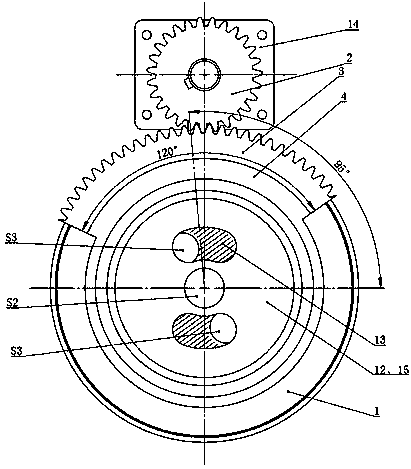
[0063] combine figure 1 and figure 2 , when the driving motor 14 drives the driving gear 3 through the output shaft, and then drives the driven gear 2 to rotate, so that the symmetrical axis of the driven gear 2 and the horizontal line of the fixed valve head 12 form a position of 45°, the effective gas outlet flow area of ​​the combustion chamber at this time S 1 The gas effective inlet flow area S of the supplementary combustion chamber 4 equal, that is, S 1 =S 2 +2S 3 =S 4 , the adjustment ratio of the effective gas outlet of the combustion chamber to the effective inlet flow area of ​​the secondary combustion chamber is 1:1, and the engine is in a low flow working state.

Embodiment 2

[0065] combine figure 1 and image 3 , the structure of this embodiment is the same as that of Embodiment 1. When the axis of symmetry of the driven gear 2 is at a 95° position to the horizontal line of the fixed valve head 12, the central hole of the rotary valve body 13 and the outlets of the two arc-shaped holes are combined. The area is equal, that is, S 2 =2S 3 , then the effective gas outlet flow area of ​​the combustor is S 1 =S 2 +2S 3 =2S 2 = S 4 , at this time, the adjustment ratio of the effective gas outlet of the combustion chamber to the effective inlet flow area of ​​the supplementary combustion chamber is 1:2, and the engine is in a medium flow working state.

Embodiment 3

[0067] combine figure 1 and Figure 4 The structural form of this embodiment is the same as that of Embodiment 1. When the axis of symmetry of the driven gear 2 is at a position of 135° to the horizontal line of the fixed valve head 12, the rotary valve body 13 is completely opposite to the two arc-shaped holes of the solid valve head. Blocking, the effective gas outlet flow area of ​​the combustion chamber is the central hole area S of the rotary valve body 13 1 =S 2 = S 4 , at this time, the adjustment ratio of the effective gas outlet of the combustion chamber to the effective inlet flow area of ​​the supplementary combustion chamber is 1:4, and the engine is in a high-flow working state.


PUM


Abstract

The invention discloses a gas flow regulation device for a rotary spray pipe value of a solid rocket-ramjet engine. Each of a first fixed part and a rotating part is provided with one central hole andtwo arc-shaped holes in the axial direction; the front end of a transmission shell and an axial outlet section of a rear sealing head shell of a combustion chamber form a dynamic sealing structure; the tail end of the transmission shell and the head end of a spray pipe shell form a dynamic sealing structure; an outer ring of a thrust self-aligning roller bearing is mounted and fixed to the interior of a shell hole in the head end of the spray pipe shell; and the inner ring of the thrust self-aligning roller bearing is fixed to a shaft neck of the tail end of the transmission shell in a matched manner. A driving motor drives a driven gear to rotate to determine a corresponding angle of a transmission ratio, and finally, drives the rotating part to rotate at a corresponding angle relative to the first fixed part, so that the two arc-shaped holes of the rotating part and the fixed part are staggered and sheltered in the axial direction, thereby changing the effective outlet circulation area of the gas of the combustion chamber and realizing gas flow regulation with determined accuracy. The gas flow regulation device for the rotary spray pipe value of the solid rocket-ramjet engine isbetter in transmission mechanism thermal protection, more compact in structure and has higher work reliability, and can realize higher-precision and larger-range gas flow regulation.

Description

technical field [0001] The invention relates to the technical field of solid rocket ramjet engines, in particular to a gas flow regulating device for a rotary nozzle valve of a solid rocket ramjet engine. Background technique [0002] With the continuous improvement of aircraft engine requirements, solid rocket ramjet has become the development direction due to its advantages of high specific impulse, small size, light weight, compact structure and low cost. The air flow into the afterburner of the solid rocket ramjet engine by ramjet changes with the flight conditions such as flight altitude, Mach number, and angle of attack, and the engine cannot keep working near the optimal air-fuel ratio. In order to ensure that the solid rocket ramjet has the best working performance and good thrust regulation ability, gas flow regulation must be carried out. [0003] At present, there are two main schemes for gas flow regulation: non-choked and blocked. In the non-choking gas flow r...

Claims


Application Information

Patent Timeline
Patent Type & Authority Applications(China)
IPC IPC(8): F02K9/86F02K9/97F02K9/32F02K9/34F02K7/18
CPCF02K7/18F02K9/32F02K9/34F02K9/343F02K9/86F02K9/97
Inventor 胡建新
Owner 湖南宏大日晟航天动力技术有限公司
Learn More