
Tool for surface treatment

A technology of surface treatment and tools, which is applied in the direction of manufacturing tools, metal processing equipment, grinding machine parts, etc., can solve the problems of product quality decline, shortened service life, and bristle density can not be adjusted, so as to improve the ability and realize the utilization Effect

Inactive Publication Date: 2020-08-25
于鑫
View PDF0 Cites 1 Cited by
  • Summary
  • Abstract
  • Description
  • Claims
  • Application Information

AI Technical Summary

Problems solved by technology

[0002] For workpieces such as metal wires, metal rods and metal pipes, in the process of processing, transportation and storage, the surface often has scale, rust, burrs, welding slag, dust and other dirt. Or before assembly, the surface of the workpiece must be cleaned, otherwise, it will not only affect the mechanical properties of the workpiece but also affect the corrosion resistance of the workpiece, resulting in a decrease in product quality and a shortened service life
At present, wire brush polishing, shot blasting and shot peening are commonly used for mechanical treatment of batch workpieces, which can remove rust and scale on the surface of workpieces, while for small workpieces and special parts of workpieces such as inner cavities, manual grinding is generally used way, the length of the bristles of the current manual polishing brush is fixed, and the density of the bristles cannot be adjusted, so it cannot adapt to the surface of complex materials

Method used


Image

  • Tool for surface treatment
  • Tool for surface treatment

Examples


Embodiment Construction

[0025] It should be understood that the specific embodiments described here are only used to explain the present invention, not to limit the present invention.

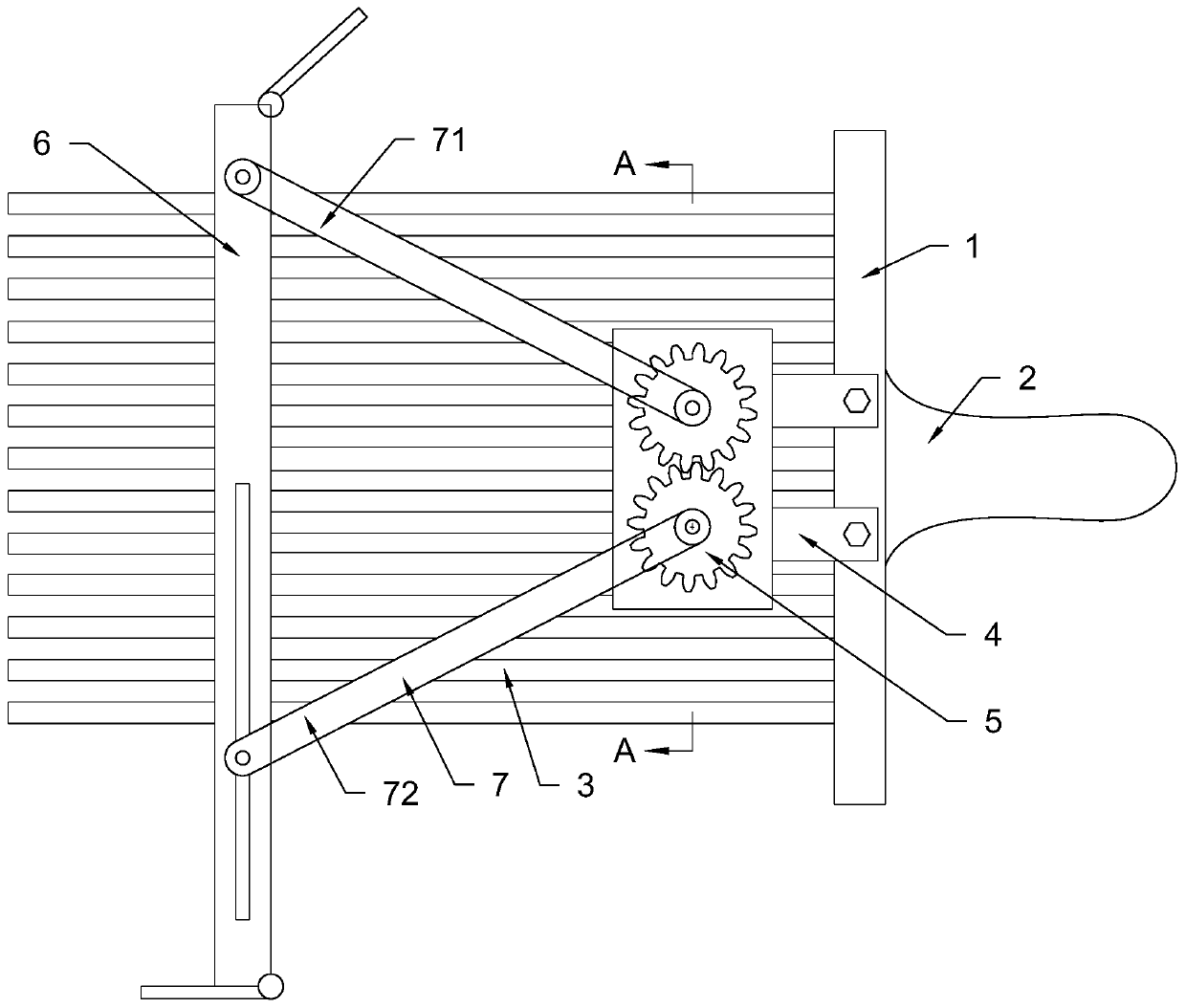
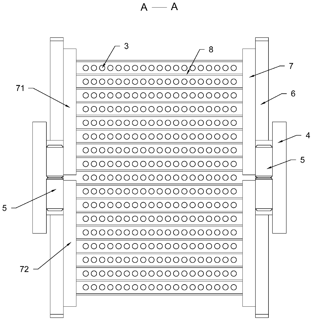
[0026] Such as figure 1 , 2 , a tool for surface treatment, including a base plate 1, a handle 2, bristles 3, a support frame 4, a gear set 5, a wire-eating adjustment plate 6, a connecting rod 7 and a round rod 8.

[0027] The cross-section of the substrate 1 is rectangular, and the substrate 1 is provided with a shaft hole; the bristles 3 are evenly arranged on the bottom surface of the substrate 1, and the material of the bristles 3 is steel wire; the handle 2 is fixed on the bottom surface of the substrate 1. Top; the number of the support frame 4 is two, the support frame 4 is symmetrically installed on the two sides of the base plate 1, and the support frame 4 and the base plate 1 are connected by bolts; the gear set 5 includes two There are two gears and these two gears mesh with each other. There are two gea...


PUM


Abstract

The invention relates to a product surface machining device, in particular to a tool for surface treatment. The tool for the surface treatment comprises a substrate, a handle, bristles, supporting frames, a gear set, a silk feeding adjusting plate, a connecting rod and round rods; the handle is arranged at the top of the substrate; the bristles are arranged at the bottom of the substrate; the supporting frames are arranged on the two side surfaces of the substrate; the gear set is arranged on the supporting frames and rotatably connected with the supporting frames; the two ends of the connecting rod are correspondingly arranged on the silk feeding adjusting plate and the gear set; the number of the round rods is several; the round rods are evenly arranged between the connecting rods; and the bristles pass through gaps between the round rods. According to the invention, by adjusting the position of the silk feeding adjusting plate, the silk feeding adjusting plate is driven to open outwards or approach inwards, the bristles between the round rods are scattered outwards or gathered inwards to change the density of the bristles and the length of silk feeding, so that the treatment ofdifferent degrees of pollution on the surface of a complex material is completed.

Description

technical field [0001] The invention relates to product surface processing equipment, in particular to a tool for surface processing. Background technique [0002] For workpieces such as metal wires, metal rods and metal pipes, in the process of processing, transportation and storage, the surface often has scale, rust, burrs, welding slag, dust and other dirt. Or before assembly, the surface of the workpiece must be cleaned, otherwise, it will not only affect the mechanical properties of the workpiece but also affect the corrosion resistance of the workpiece, resulting in a decrease in product quality and a shortened service life. At present, wire brush polishing, shot blasting and shot peening are commonly used for mechanical treatment of batch workpieces, which can remove rust and scale on the surface of workpieces, while for small workpieces and special parts of workpieces such as inner cavities, manual grinding is generally used Mode, the length of the bristles of the c...

Claims


Application Information

Patent Timeline
Patent Type & Authority Applications(China)
IPC IPC(8): B24B27/033B24B23/00B24B41/04B24B47/22B24B47/20
CPCB24B23/00B24B27/033B24B41/04B24B47/20B24B47/22
Inventor 于鑫
Owner 于鑫
Learn More