Forced centering device for precision engineering measurement

A technology of forced centering and precision engineering. It is used in measuring devices, measuring instruments, surveying and mapping, and navigation. It can solve the problems of difficulty in opening again, inconvenient disassembly and assembly, and inability to adjust the structure again, so as to increase stability and ensure stability. Effect

Active Publication Date: 2020-08-18
JIANGSU SECURITY TECH CARRER ACADEMY
View PDF7 Cites 0 Cited by
  • Summary
  • Abstract
  • Description
  • Claims
  • Application Information

AI Technical Summary

Problems solved by technology

[0003] At present, there are the following problems in the existing centering device: 1. The existing centering device is generally placed directly on the ground when it is fixed, and it is easy to shake so that the measurement accuracy cannot be guaranteed. At the same time, the screws in the forced centering device are generally set On the outside, it is not easy to open again after long-term use, and it is not convenient to disassemble and assemble the screws inside the observation pier; 2. After the traditional centering device is installed and fixed, its structure cannot be adjusted again, which cannot meet the use of measuring instruments

Method used


Image

  • Forced centering device for precision engineering measurement
  • Forced centering device for precision engineering measurement
  • Forced centering device for precision engineering measurement

Examples


Embodiment Construction

[0024] The following will clearly and completely describe the technical solutions in the embodiments of the present invention with reference to the accompanying drawings in the embodiments of the present invention. Obviously, the described embodiments are only some, not all, embodiments of the present invention. Based on the embodiments of the present invention, all other embodiments obtained by persons of ordinary skill in the art without making creative efforts belong to the protection scope of the present invention.

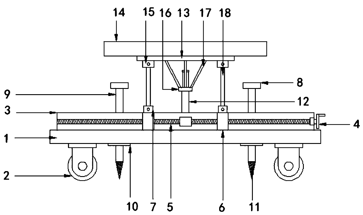
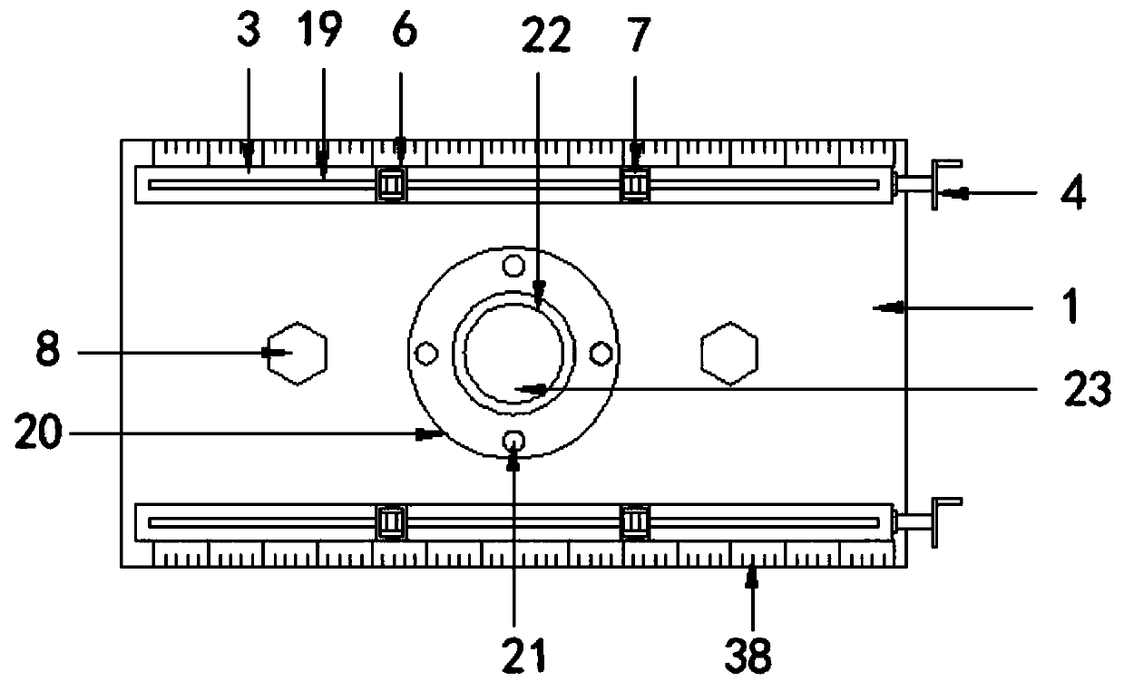
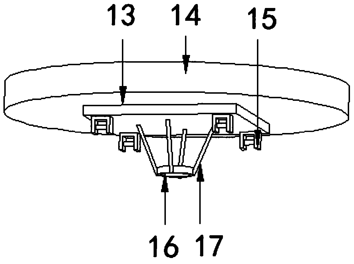
[0025] see Figure 1-7 , the present invention provides a technical solution: a forced centering device for precision engineering measurement, comprising: a fixed plate 1, a box body 3 is provided on the upper part of the fixed plate 1 and two groups of boxes are provided on the box body 3, and the box body 3 They are parallel to each other and installed on the upper and lower ends of the fixed plate 1. The inside of the box body 3 is provided with a screw rod...


PUM


Abstract

The invention discloses a forced centering device for precision engineering measurement. The forced centering device comprises a fixing plate, two groups of box bodies are arranged at the upper part of the fixing plate; the box bodies are parallel to each other and are installed at the upper end and the lower end of the fixing plate. A screw is arranged in each box body, a crank is arranged on theright side of the screw, a sliding block is arranged on the surface of the screw, a sliding groove is formed in the surface of each box body, the sliding block is slidably connected with the slidinggroove, a first movable shaft is arranged on the upper portion of the sliding block, a lifting rod is arranged in the first movable shaft, and a second movable shaft is arranged on the upper portion of the lifting rod. The supporting rods and the limiting rings are arranged on the lower portion of the mounting plate, and the limiting rings sleeves the surface of the telescopic rods;; due to the fact that the centering column structure is fixed, the balance of the centering disc can be guaranteed through the limiting rings, meanwhile, the surface of the silicon chip is provided with an embedding groove and a second threaded hole which are used for instrument connection, the silicon chip is connected with the first threaded column through the cover plate, and the protection effect is achieved when the silicon chip is not used.

Description

technical field [0001] The invention relates to the technical field of engineering measurement, and more specifically relates to a forced centering device for precision engineering measurement. Background technique [0002] Engineering survey is an important part of engineering construction, including control survey and topographic survey in the planning and design stage, construction survey, equipment installation survey and completion survey in the construction stage, deformation survey in the operation and management stage, etc. For large-scale projects and special projects, such as railways, tunnels, mines, bridges, and national defense projects, precision engineering measurement is required to meet the high standard requirements of engineering construction, positioning or deformation observation. In order to ensure the high precision of the observation data and the reliability of the results, precision engineering surveys generally do not use traditional temporary tripo...

Claims


Application Information

Patent Timeline
Patent Type & Authority Applications(China)
IPC IPC(8): G01C15/00
CPCG01C15/00
Inventor 史先领沈兆振
Owner JIANGSU SECURITY TECH CARRER ACADEMY
Why Eureka
Try Eureka