
Nozzle type catalytic muffler for automobile diesel engine

A diesel engine, catalytic muffler technology, applied in the direction of engine components, combustion engines, machines/engines, etc., can solve the problems of adverse environmental impact, long exhaust pipe, large space occupation, etc., to reduce emissions, save space, and save energy energy effect

Active Publication Date: 2020-08-18
安阳职业技术学院
View PDF5 Cites 0 Cited by
  • Summary
  • Abstract
  • Description
  • Claims
  • Application Information

AI Technical Summary

Problems solved by technology

[0004] At present, the SCR exhaust after-treatment system used by diesel engines on the market requires an additional Tianlan injection device. The engine exhaust is treated by catalytic reduction. Most of the existing diesel engines arrange the blue nozzle on the exhaust pipe behind the engine booster. The blue and the exhaust gas are mixed through a certain length of exhaust pipe before entering the SCR catalytic muffler. In order to ensure the full mixing of the blue and the exhaust gas, the exhaust pipeline needs to have a sufficient length, which leads to the existing diesel engine automobile exhaust pipeline is relatively long, takes up a large space, and has a high cost
[0005] In addition, investigations and studies have shown that only about one-third of the energy released by automobile fuel combustion is effectively used, and the rest of the energy is lost or emitted into the atmosphere, resulting in a great waste of energy and adverse environmental impacts

Method used


Image

  • Nozzle type catalytic muffler for automobile diesel engine

Examples


Embodiment Construction

[0026] The present invention will be further described in detail below in conjunction with the accompanying drawings.

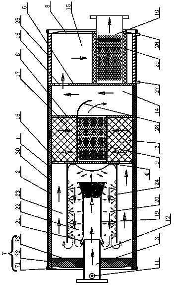
[0027] Such as figure 1As shown, a nozzle-type catalytic muffler for an automobile diesel engine includes an inner cylinder 2, an outer cylinder 1, an intake pipe 3, a deflector, a first baffle 4, a second baffle 5, a third baffle 6, The front end cover 7, the rear end cover 8, the middle pipe 9 and the air outlet pipe 10, the front end cover 7 and the rear end cover 8 are respectively arranged at the two ends of the outer cylinder body 1, and the front end cover 7, the rear end cover 8 and the outer cylinder body 1 A cylindrical structure with both ends of the siege closed, the front end cover 7 includes an outer end cover 71 , an insulating layer 72 and an inner partition 73 arranged in sequence from outside to inside. The outer cylinder 1 is provided with an inner cylinder 2, the inner cylinder 2 is provided with a first partition 4, a second partition 5 ...


PUM


Abstract

The invention relates to a nozzle type catalytic muffler for an automobile diesel engine. The nozzle type catalytic muffler is characterized in that an adblue nozzle is arranged on an air inlet pipe outside the SCR catalytic muffler, and meanwhile, a flow guide device for changing the air flow direction is arranged in the muffler; by changing the air flow direction, tail gas and a high-purity ureasolution for a vehicle are fully mixed and then subjected to catalytic reduction treatment, so that the length of an exhaust pipeline of the engine is shortened, space is saved, and cost is reduced;in addition, heat preservation layers are arranged outside an air inlet cavity and a catalytic cavity of the catalytic muffler, the heat preservation effect on the tail gas is achieved, and a catalytic reduction reaction is facilitated; and a cooling flow channel for cooling water to flow is arranged outside an exhaust cavity of the catalytic muffler, cooling water in the cooling flow channel andan automobile heating system are arranged in the cooling flow channel, waste heat in the tail gas is used for providing a heat source for the automobile heating system, and therefore the purposes of saving energy and reducing emission are achieved.

Description

Technical field: [0001] The invention belongs to the technical field of automobile exhaust emission mufflers, and in particular relates to a nozzle type catalytic muffler for automobile diesel engines. Background technique: [0002] With the development of the automobile industry and the enhancement of people's purchasing power, the production and ownership of automobiles in my country has gradually increased, and the pollution caused by automobile exhaust has become more and more serious. With the improvement of people's awareness of environmental protection, automobile exhaust pollution has become the most important issue in my country control pollution problems. [0003] With the improvement of environmental protection requirements, the emission standards of automobile engines have been gradually upgraded, and most engines with emission standards above China IV and China V have begun to use SCR exhaust after-treatment systems. The system needs Tianlan, Tianlan refers to t...

Claims


Application Information

Patent Timeline
IPC IPC(8): F01N3/28F01N3/20F01N1/02F01N1/24F01N5/02B60H1/20
CPCF01N3/2885F01N3/2889F01N3/2892F01N3/2066F01N1/02F01N1/24F01N5/02B60H1/20F01N2610/02F01N2570/14Y02A50/20Y02T10/12
Inventor 程新龙陈希李通王峰伟郭贺洋
Owner 安阳职业技术学院
Learn More