
Proximity sensor inductance resolving method

A proximity sensor and inductance technology, applied in the field of proximity sensors, can solve problems such as poor low temperature indicators, difficult operation, and not suitable for mass production, so as to improve production efficiency and precision, avoid high and low temperature errors, and solve long-term measurement accuracy drift Effect

Active Publication Date: 2020-08-14
西安润鑫航空科技有限公司
View PDF3 Cites 4 Cited by
  • Summary
  • Abstract
  • Description
  • Claims
  • Application Information

AI Technical Summary

Problems solved by technology

[0005] The main disadvantage of this method is that in production, each sensor needs to pass through a dedicated displacement platform, and take voltage sampling at room temperature and high temperature with a step of 0.04mm within the distance range of the application, and finally burn it into the FPGA. Curve fitting is carried out through the room temperature and high temperature values ​​sampled at the same location, and finally multiple curves are obtained, and the secondary process is defined as sensor calibration
At present, the low temperature drift of domestic coils is generally too large, that is, the inductance values ​​at low temperature and normal temperature are quite different. Since this digital pulse method calibrates the fitting curve at room temperature and high temperature, it is speculated that the value at low temperature is in the fitting curve, and it is actually proved that the low temperature test is accurate. The index deviation is large, which does not meet the high-precision requirements. Even if the algorithm can be compensated and optimized, due to the differences in the characteristics of each sensor, it needs to be compensated separately. The actual operation is difficult and is not conducive to industrial production.
[0006] Summary The advantage of the digital pulse method is that it is simple in design; the main disadvantage is that it is not suitable for mass production; the low temperature index is poor, and it does not meet the full temperature working performance requirements

Method used


Image

  • Proximity sensor inductance resolving method
  • Proximity sensor inductance resolving method
  • Proximity sensor inductance resolving method

Examples


Embodiment Construction

[0031] The method for calculating the inductance of the proximity sensor according to the present invention will be described in detail below with reference to the drawings and embodiments.

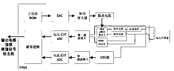
[0032] The method for solving the inductance of the proximity sensor in the present invention generates a digital waveform with adjustable amplitude and frequency through the excitation waveform module, and sends it to the proximity sensor after being driven by the coil excitation circuit; after the electrical feedback signal of the proximity sensor is detected and sampled, the The digital method is fed back to the calculation algorithm; the resistance and inductance parameters of the coil are directly separated by the calculation algorithm.

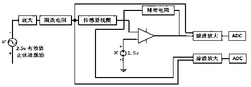
[0033] Such as figure 1 As shown, the main chip FPGA controls the DAC to generate a sine wave excitation signal through the SPI bus, and then excites the proximity sensor coil through the amplifier and current limiting. FPGA controls the conduction...


PUM


Abstract

An inductance resolving method for a proximity sensor belongs to the field of proximity sensors and is characterized in that a digital waveform with adjustable amplitude and frequency is generated through an excitation waveform module, and is sent to the proximity sensor after being driven by a coil excitation circuit; an electric feedback signal of the proximity sensor is fed back to the resolving algorithm in a digital mode after being detected and sampled; resistance and inductance parameters of the coil are directly separated through a resolving algorithm. A proximity sensor and a calibration load are switched by using multiple channels; the calibration load comprises a short circuit resistor, an open circuit resistor and a standard resistor, and the proximity sensor is driven by usinga low-frequency sine wave, so that the influence of distributed capacitance of a connecting cable connected with the inductive proximity sensor in series on the measurement precision can be ignored,and the problems of long-time measurement precision drift and sensitivity to the length of the cable of a sensor measurement circuit are effectively solved; meanwhile, the inductance value is obtainedby calculating the impedance of the inductor, and the high-low temperature error problem is avoided.

Description

technical field [0001] The invention belongs to the field of proximity sensors, in particular to a method for calculating the inductance of an inductive proximity sensor applied to aviation airborne equipment. Background technique [0002] At present, the inductive proximity sensors used in aircraft can be divided into variable reluctance type and eddy current loss type according to the different excitation signals. The signal of the inductive proximity sensor using the principle of variable reluctance is processed by the remote signal processing unit as a discrete signal, which is customarily called a proximity sensor; the excitation signal of the proximity sensor is an AC signal, and the metal target is detected using variable reluctance technology , consisting of a coil and a magnetic core, the detection object is a metal target of soft magnetic material. When the target moves to the proximity sensor, the change of the air gap thickness causes the reluctance of the coil c...

Claims


Application Information

Patent Timeline
Patent Type & Authority Applications(China)
IPC IPC(8): H03K17/945
CPCH03K17/945
Inventor 陶慧斌
Owner 西安润鑫航空科技有限公司
Learn More