Electric automation reinforcing steel bar straightening machine

A technology of electrical automation and steel bars, applied in the direction of grinding drive devices, grinding machine parts, coatings, etc., can solve problems such as single function, increased corrosion, and cuts on workers' palms

Inactive Publication Date: 2020-08-14
武汉船舶职业技术学院
View PDF8 Cites 7 Cited by
  • Summary
  • Abstract
  • Description
  • Claims
  • Application Information

AI Technical Summary

Problems solved by technology

[0003] The existing mainstream steel bar straightening machine in the construction industry has a single function and can only perform the straightening function alone, and cannot perform rust removal and anti-rust treatment on the straightened steel bars. After straightening, a large amount of iron tends to remain on the surface It is very easy to cut the palm of the worker when the subsequent worker carries it, and the steel bar that has not been derusted is used for subsequent construction. In rainy weather or in a humid area, the corrosion will intensify and eventually affect the service life of the building

Method used


Image

  • Electric automation reinforcing steel bar straightening machine
  • Electric automation reinforcing steel bar straightening machine
  • Electric automation reinforcing steel bar straightening machine

Examples


Embodiment Construction

[0028] In order to make the technical means, creative features, goals and effects achieved by the present invention easy to understand, the present invention will be further described below in conjunction with specific embodiments.

[0029] In the description of the present invention, it should be noted that the terms "upper", "lower", "inner", "outer", "front end", "rear end", "both ends", "one end", "another end" The orientation or positional relationship indicated by etc. is based on the orientation or positional relationship shown in the drawings, and is only for the convenience of describing the present invention and simplifying the description, rather than indicating or implying that the referred device or element must have a specific orientation, use a specific Azimuth configuration and operation, therefore, should not be construed as limiting the invention. In addition, the terms "first" and "second" are used for descriptive purposes only, and should not be understood ...


PUM


Abstract

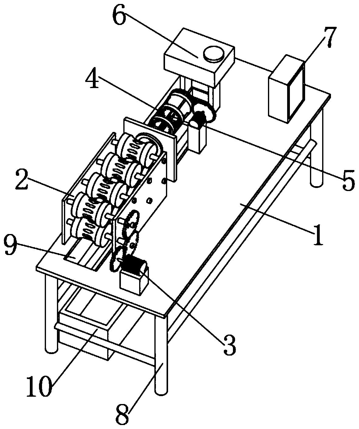
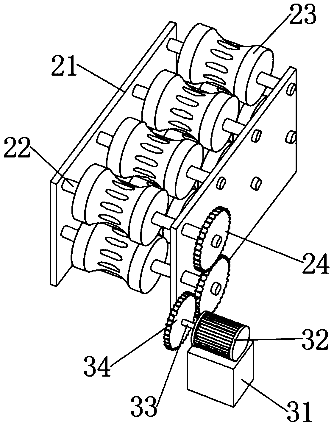
The invention discloses an electric automation reinforcing steel bar straightening machine, which comprises a workbench and a collection box, wherein the front part of the upper end of the workbench is fixedly provided with a straightening device, a rust removal device and an oil coating device; the straightening device, the rust removal device and the oil coating device are arranged in sequence from left to right; a position, which is positioned behind the straightening device, of the upper end of the workbench is provided with a first driving mechanism; a position, which is positioned behindthe rust removal device, of the upper end of the workbench is provided with a second driving mechanism; the right rear corner of the workbench is fixedly provided with an electronic control box; thelower end of the workbench is fixedly provided with a supporting frame; the upper end of the workbench is provided with a blanking groove which is vertically through; and an opening on the upper end of the collection box is positioned just below the blanking groove. The electric automation reinforcing steel bar straightening machine disclosed by the invention combines working procedures, includingreinforcing steel bar straightening, reinforcing steel bar rust removal, reinforcing steel bar straightening rust prevention and the like, into a whole, working efficiency can be greatly improved, better economic benefits can be brought, and the electric automation reinforcing steel bar straightening machine is suitable to be popularized and utilized.

Description

technical field [0001] The invention relates to the technical field of steel bar straightening and processing equipment, in particular to an electric automatic steel bar straightening machine. Background technique [0002] Steel bar refers to steel for reinforced concrete and prestressed reinforced concrete. Its cross section is circular, sometimes square with rounded corners, including smooth round steel bars, ribbed steel bars, and twisted steel bars. Plain round steel bars are actually ordinary low-profile steel bars. Carbon steel small round steel and disc round, deformed steel bars are steel bars with ribs on the surface, usually with two longitudinal ribs and transverse ribs evenly distributed along the length direction, and the shape of the transverse ribs is spiral, herringbone, and crescent. Firstly, most of the round steel bars are rolled into a disc shape. When they need to be used, they must be straightened before they can be used. This requires the use of steel ...

Claims


Application Information

Patent Timeline
Patent Type & Authority Applications(China)
IPC IPC(8): B21F1/02B24B27/033B24B41/04B24B47/12B24B47/20B24B55/12B05C1/06B05C11/10
CPCB21F1/02B24B27/033B24B41/04B24B47/12B24B47/20B24B55/12B05C1/06B05C11/10
Inventor 邹新宇汪洋
Owner 武汉船舶职业技术学院
Why Eureka
Try Eureka