Anesthesiology disinfection device

A disinfection device and anesthesiology technology, applied in the medical field, can solve the problems of low disinfection efficiency, poor device performance variability, increased operation energy consumption, etc., to ensure work efficiency and disinfection effect, increase disinfection effect and cleaning effect, and avoid electricity. Consumption and cost effect

Active Publication Date: 2021-05-11
李昌法
View PDF10 Cites 0 Cited by
  • Summary
  • Abstract
  • Description
  • Claims
  • Application Information

AI Technical Summary

Problems solved by technology

[0003] The existing patent No. CN106822946A proposes an anesthesia mask disinfection device, which solves the problems of low disinfection efficiency, poor disinfection effect and easy loss during the disinfection process, but the above-mentioned device utilizes structures such as an ultrasonic generator, a disinfection controller and a water pumping device In many use cases, the mask only needs to be soaked and disinfected with disinfectant to meet the use standard. The above-mentioned device greatly increases the cost of the equipment and the energy consumption of operation, and has poor practicability.
[0004] The existing patent No. CN102389581B proposes a disinfection machine, which is sterilized by mechanisms such as a cleaning and disinfection box, a circulating flushing pressure pump, an inner wall flushing nozzle, and an automatic rotating spray mechanism, but the above-mentioned device has the problem of poor performance, because the mask The amount of use is large, so the amount of disinfection is also large. When the above-mentioned device needs to increase the processing capacity without reducing the processing efficiency, it is necessary to add or use a higher-power water pump and vibration motor, which greatly increases the cost. while increasing the operating energy consumption

Method used


Image

  • Anesthesiology disinfection device
  • Anesthesiology disinfection device
  • Anesthesiology disinfection device

Examples


Embodiment 1

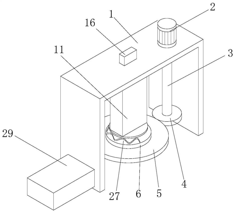
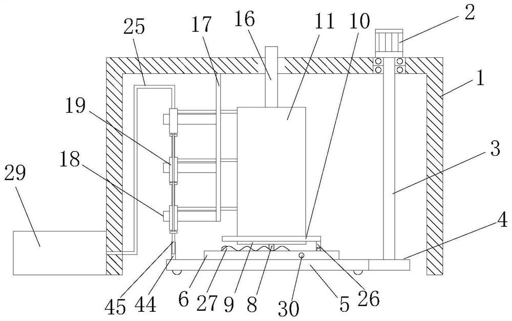
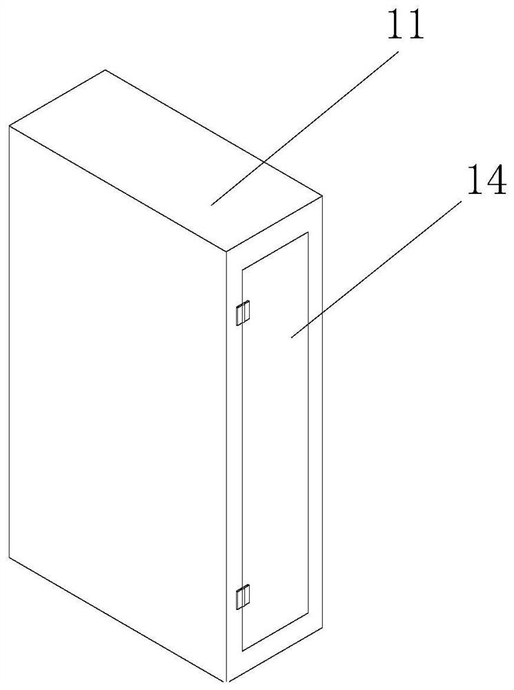
[0042] Example 1: Please refer to Figure 1-7 , an anesthesiology department disinfection device, comprising a frame 1 and a disinfection box 11, the frame 1 is a rectangular body hollowed out on the bottom surface, a rotating motor 2 is fixedly installed on the right side of the top surface of the frame 1, and the transmission shaft of the rotating motor 2 is located below the inner wall of the frame 1 and A transmission rod 3 is fixedly connected, and the end of the transmission rod 3 away from the rotating motor 2 is fixedly connected with a spur gear A4, and the left outer wall of the spur gear A4 is meshed with a chassis A5, and the chassis A5 is cylindrical and has tooth grooves on the outer wall. The top surface is fixedly connected with the chassis B6, and the center of the top surface of the chassis B6 is provided with a socket 7, which is a straight hole and penetrates through the chassis A5, and the inner wall of the socket 7 is sleeved with an insertion rod 8, and t...

Embodiment 2

[0045] Example 2: Please refer to Figure 8-10 , on the basis of Embodiment 1, the number of cylinders A19 on a single connection plate 18 is three and distributed left and right, the left side of the frame 1 is fixedly connected with the box body B40 and the box body C41, and the box body A29, the box body The body B40 and the box body C41 communicate with the round platform holes 22 at the top of the three cylinders A19 through connecting pipes 25 respectively. A groove is opened on the top surface of the chassis A5 and a telescopic motor 43 is fixedly installed in the groove. The transmission shaft of the telescopic motor 43 and the roller frame 44 is fixedly connected, and the telescopic motor 43 is fixedly installed with three sensors 42 in the slot installed on the chassis A5, and the three sensors 42 correspond to the positions of the three cylinders A19. Different disinfectants use the control circuit to control the expansion and contraction of the telescopic motor 43,...

Embodiment 3

[0047] Example 3: Please refer to Figure 11-14, On the basis of Embodiment 1, the corresponding clamp ring 13 positions on the left side of the disinfection tank 12 are provided with a discharge groove 55, and the shape of the discharge groove 55 is oblique rectangle (such as Figure 13 As shown), the position corresponding to the clamp ring 13 on the right side of the disinfection tank 12 is provided with a feed tank 54. Be positioned at disinfection box 11 fronts (as Figure 14 shown), the right side of the disinfection box 11 is provided with a movable groove 47 above the disinfection groove 12, the center inner wall of the movable groove 47 is fixedly connected with a slide bar 48, and the outer wall of the slide bar 48 is sleeved with a sleeve 49, and the sleeve 49 The bottom surface of the sleeve 49 is fixedly connected with a return spring A50, and the end of the return spring A50 away from the sleeve 49 is fixedly connected with the bottom surface of the movable groo...


PUM


Abstract

The invention relates to the field of medical technology, and discloses a disinfection device for the department of anesthesiology, which includes a frame and a disinfection box. A rotating motor is fixedly installed on the right side of the top surface of the frame, and a transmission shaft of the rotating motor is fixedly connected with a transmission rod. One end is fixedly connected with a spur gear A, the left outer wall of the spur gear A is meshed with a chassis A, the top surface of the chassis A is fixedly connected with a chassis B, the center of the top surface of the chassis B is provided with a socket, and the inner wall of the socket is sleeved with a socket. Rod, the top surface of the insertion rod is fixedly connected with the chassis C, the top surface of the chassis C is socketed with the chassis D, the top surface of the chassis D is fixedly connected with the disinfection box, through the setting of the disinfection box, the rotating motor is used as a unified power source, The transportation of disinfectant and the shaking function of the disinfection box are realized, and the power consumption and cost generated by the use of water pumps and vibrating motors are avoided. Moreover, the working mode of the device does not need to be added or use higher-power mechanisms during capacity expansion. Can guarantee work efficiency and disinfection effect.

Description

technical field [0001] The invention relates to the field of medical technology, in particular to a disinfection device for the department of anesthesiology. Background technique [0002] In the endotracheal intubation anesthesia process, the patient needs to wear a mask, and after the anesthesia is over, the used mask needs to be disinfected for subsequent use. [0003] The existing patent No. CN106822946A proposes an anesthesia mask disinfection device, which solves the problems of low disinfection efficiency, poor disinfection effect and easy loss during the disinfection process, but the above-mentioned device utilizes structures such as an ultrasonic generator, a disinfection controller and a water pumping device However, in many usage situations, the face mask only needs to be soaked and disinfected with a disinfectant solution to meet the use standard. The above-mentioned device greatly increases the cost and energy consumption of the equipment, and has poor practicabi...

Claims


Application Information

Patent Timeline
Patent Type & Authority Patents(China)
IPC IPC(8): B08B3/04B08B1/02B08B13/00F26B11/02F26B21/00A61L2/18
CPCA61L2/18B08B1/02B08B3/044B08B13/00F26B11/02F26B21/001F26B21/004
Inventor 李昌法韩寒魏国平王颖
Owner 李昌法
Why Eureka
Try Eureka