
Projection device based on surface emitting laser and manufacturing method thereof

A surface-emitting laser, surface-emitting laser technology, applied in projection devices, optics, instruments, etc., to achieve the effect of reducing volume and weight, reducing assembly difficulty, and avoiding volume

Active Publication Date: 2020-08-11
无锡奥普顿光电子有限公司
View PDF5 Cites 9 Cited by
  • Summary
  • Abstract
  • Description
  • Claims
  • Application Information

AI Technical Summary

Problems solved by technology

TOF projection modules usually include several main components such as VCSEL lasers, collimator lenses, and DOE devices, and also face the problem of module miniaturization

Method used


Image

  • Projection device based on surface emitting laser and manufacturing method thereof
  • Projection device based on surface emitting laser and manufacturing method thereof
  • Projection device based on surface emitting laser and manufacturing method thereof

Examples


Embodiment Construction

[0054] For a better understanding of the application, various aspects of the application will be described in more detail with reference to the accompanying drawings. It should be understood that these detailed descriptions are descriptions of exemplary embodiments of the application only, and are not intended to limit the scope of the application in any way. Throughout the specification, the same reference numerals refer to the same elements. The expression "and / or" includes any and all combinations of one or more of the associated listed items.

[0055] It should be noted that in this specification, expressions of first, second, etc. are only used to distinguish one feature from another, and do not represent any limitation on the features. Accordingly, a first body discussed hereinafter may also be referred to as a second body without departing from the teachings of the present application.

[0056]In the drawings, the thickness, size and shape of objects have been slightl...


PUM

PropertyMeasurementUnit
reflectanceaaaaaaaaaa

Abstract

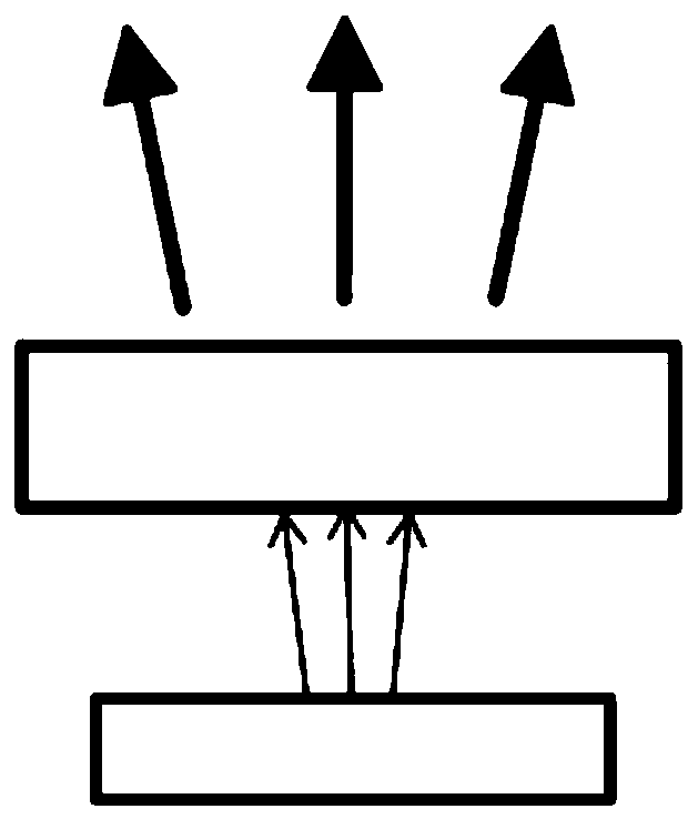
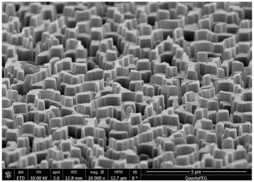
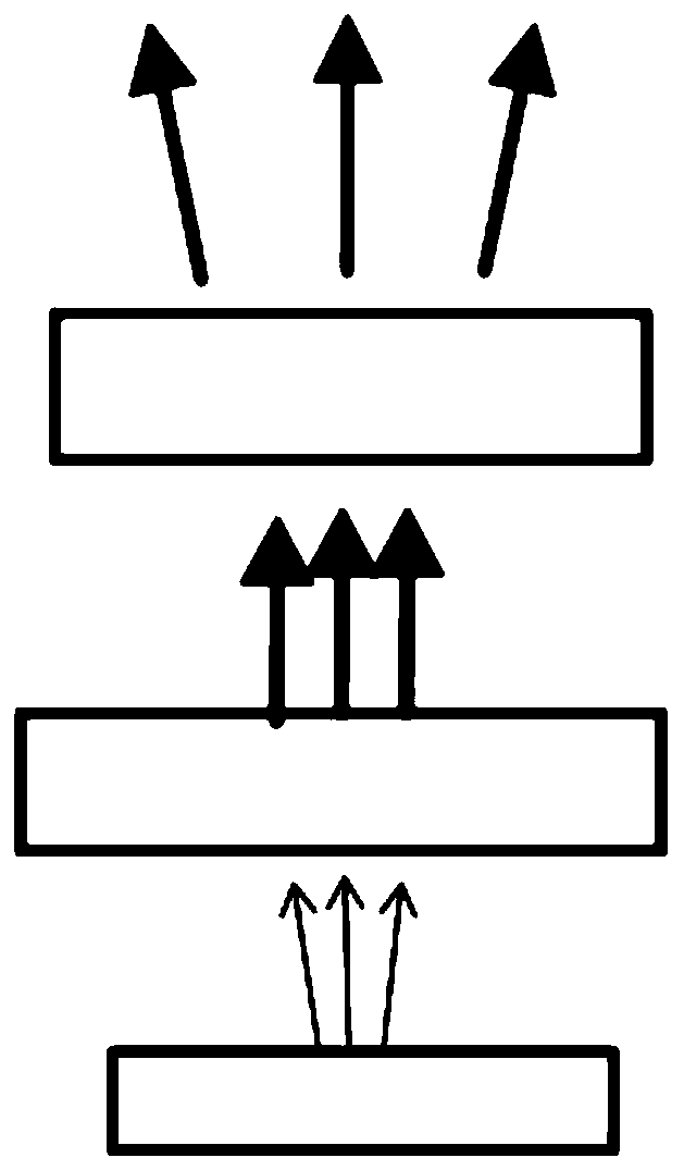
The invention provides a projection device based on surface emitting laser. The device comprises a surface emitting laser which can emit a needed plane pattern, and an integrated diffractive optical element, wherein the integrated diffractive optical element is arranged at a front end of the surface emitting laser, a surface of the integrated diffractive optical element is provided with an embossed microstructure, the shape of the integrated diffractive optical element is determined by a fused phase transformation function, and the fused phase transformation function is obtained by fusing a lens function of a virtual collimating lens and a phase transformation function of an original diffractive optical element. The invention further provides a manufacturing method of the corresponding projection device based on the surface emitting laser. The device is advantaged in that an entity collimating lens can be omitted, so miniaturization of a projection module is facilitated.

Description

technical field [0001] The present application relates to technical fields such as optical elements, diffractive optics, three-dimensional sensing, and laser projection. In particular, the present application relates to a surface-emitting laser-based projection device and a manufacturing method thereof. Background technique [0002] With the rapid development of optical technology, especially the rapid development of technical branches such as optical components and diffractive optics, three-dimensional sensing (3D sensing) devices have become increasingly mature. In recent years, more and more devices equipped with three-dimensional Sensing devices for consumer electronics end products. For example, the 3D camera module (sometimes also called 3D camera module) used for face recognition in Apple mobile phones is a typical three-dimensional sensing device. The 3D camera module uses a vertical cavity surface emitting laser (VCSEL). Hundreds of laser beams emitted by the verti...

Claims


Application Information

Patent Timeline
Patent Type & Authority Applications(China)
IPC IPC(8): G03B21/20
CPCG03B21/2013G03B21/2033G03B21/208
Inventor 刘劲松
Owner 无锡奥普顿光电子有限公司
Learn More