Anti-blocking massage shower head

An anti-clogging and shower technology, applied in the field of sanitary ware, can solve the problems of bristle falling off and clogging nozzle holes, and low brush cleaning degree, so as to achieve the effect of increasing applicability, increasing cleaning degree and increasing comfort

Inactive Publication Date: 2020-08-11
郭春燕
View PDF11 Cites 2 Cited by
  • Summary
  • Abstract
  • Description
  • Claims
  • Application Information

AI Technical Summary

Problems solved by technology

[0004] The purpose of the present invention is to solve the shortcomings of the prior art that the degree of brushing is low and the bristles fall off to block the nozzle hole, and propose an anti-clogging massage shower head

Method used


Image

  • Anti-blocking massage shower head
  • Anti-blocking massage shower head
  • Anti-blocking massage shower head

Examples


Embodiment 1

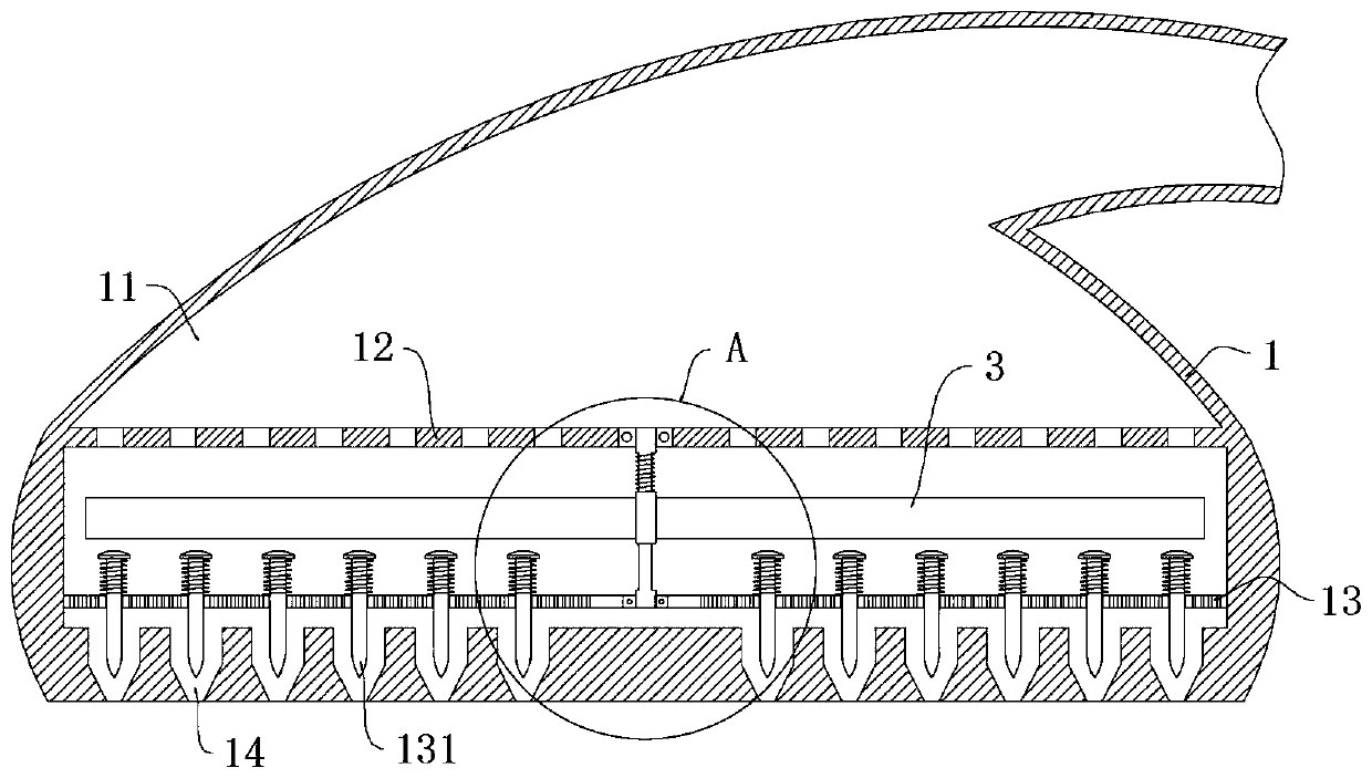
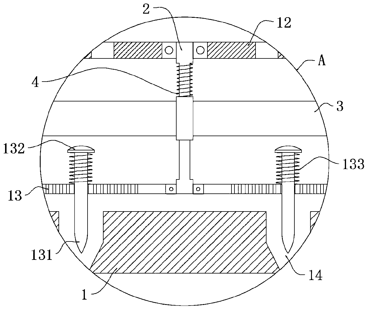
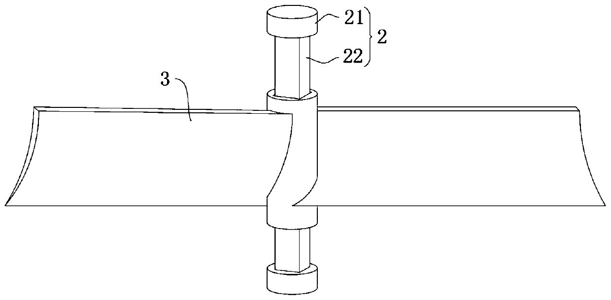
[0024] refer to Figure 1-3 , an anti-clogging massage shower head, comprising a shower head 1, the shower head 1 includes a water inlet chamber 11, a first porous plate 12 and a second porous plate 13 are respectively installed in the water inlet chamber 11 from top to bottom, the first A rotating shaft 2 is mounted on the first porous plate 12 and the second porous plate 13 to rotate together. The rotating shaft 2 includes two discs 21 and a square column 22. The square column 22 is slidably equipped with an arc-shaped fan blade 3, and the arc-shaped fan blade 3 and the upper disc 21 is installed with a first spring 4, a plurality of water spray holes 14 are opened on the shower head 1, and a plurality of plugging pins 131 are slidingly inserted in the second porous plate, and the upper end of each plugging pin 131 Limiting pieces 132 are installed, and a second spring 133 is installed between each limiting piece 132 and the second porous plate 13;

[0025] After the water ...

Embodiment 2

[0029] refer to Figure 4-5 , an anti-clogging massage shower, which is basically consistent with Embodiment 1, the difference is that:

[0030] An adjustment knob 5 is mounted on the central screw thread of the lower bottom surface of the shower head 1, and the adjustment knob 5 is in contact with the lower end of the rotating shaft 2;

[0031] By rotating the adjusting knob 5, the contact friction force between the adjusting knob 5 and the lower end of the rotating shaft 2 can be adjusted. When the adjusting knob 5 is in tight contact with the lower end of the rotating shaft 2, the friction force increases, and the arc-shaped fan blade 3 rotates at a slower speed. , the pulse water flow frequency is low, when the adjustment knob 5 is in loose contact with the lower end of the rotating shaft 2, the friction force decreases, and the arc-shaped fan blade 3 rotates faster, and the pulse water flow frequency is higher, which can be adjusted according to the skin of different grou...


PUM


Abstract

The invention discloses an anti-blocking massage shower head. The anti-blocking massage shower head comprises a shower head body, the shower head body comprises a water inlet cavity, a first porous plate and a second porous plate are installed in the water inlet cavity from top to bottom, a rotating shaft is rotationally installed on the first porous plate and the second porous plate jointly, andthe rotating shaft comprises two discs and a square column; arc-shaped fan blades are installed on the square column in a sliding mode, first springs are installed between the arc-shaped fan blades and an upper-layer disc, a plurality of water spraying holes are formed in the shower head, and a plurality of blocking needles are inserted into the second porous plate in a sliding mode. The arc-shaped fan blades are pushed by water flow to rotate and press the blocking needles downwards, so that the blocking needles can penetrate into the water spraying holes to clean scale impurities, the cleaning degree is increased, the blocking needles sequentially block the water spraying holes in a rotating and pressing process of the arc-shaped fan blades to form massage pulse water flow, and the shower comfort is improved; the massage frequency is adjusted by adjusting a rotating speed of the arc-shaped fan blades through an adjusting knob, and the applicability of the shower head is improved.

Description

technical field [0001] The invention relates to the field of sanitary ware, in particular to an anti-clogging massage shower. Background technique [0002] Every family has a bathroom. The shower in the bathroom is a common bathroom product. The shower shower is usually a hot water bath. The hot water mostly comes from domestic tap water. After the tap water is heated, it is easy to produce scale, so the shower will spray when used for a long time. Pore ​​clogging. [0003] Existing anti-clogging showers mostly use the cleaning method, that is, a rotating brush is installed in the shower to scrub the nozzle holes, but the scale impurities in the nozzle holes are relatively deep, and the horizontal rotating brush of the brush cannot effectively clear the nozzle holes. If the brush is used in water for a long time, the bristles will fall off, and the bristles that fall off are more likely to block the nozzle hole. Contents of the invention [0004] The purpose of the prese...

Claims


Application Information

Patent Timeline
Patent Type & Authority Applications(China)
IPC IPC(8): B05B1/08B05B15/522B05B12/00A61H9/00
CPCA61H9/0007A61H9/0021B05B1/08B05B12/002B05B15/5225
Inventor 郭春燕吴军
Owner 郭春燕
Why Eureka
Try Eureka