
Brake magnetic pole structure for linear eddy current brake device

A magnetic pole structure and braking force technology, which is applied in the field of rail vehicle braking systems, can solve the problems of increasing the slot full rate and ampere-turns, short-circuit failure, and increasing the current density of aluminum wires with the aluminum film wire winding coil technology, and achieves the goal of product The effects of increased consistency and reliability, improved packaging strength, and reduced packaging difficulty

Pending Publication Date: 2020-08-07
NANJING CRRC PUZHEN HAITAI BRAKE EQUIP CO LTD
View PDF0 Cites 0 Cited by
  • Summary
  • Abstract
  • Description
  • Claims
  • Application Information

AI Technical Summary

Problems solved by technology

[0005] Thin-film aluminum wire winding coil technology: on the basis of the existing scheme, increase the number of turns and reduce the cross-sectional area of ​​the aluminum film. In this way, the current density of the aluminum wire increases, which is easy to burn out the coil, resulting in brake failure and serious consequences.
Reducing the thickness of the insulating diaphragm can also increase the slot full rate, but the current diaphragm thickness is equivalent to the thickness of the enameled wire paint film, and if the thickness is reduced, the dielectric strength is difficult to guarantee, and it is easy to cause short circuit failure
Aluminum film wire wound coil technology is extremely difficult and challenging in terms of increasing the slot full rate and ampere-turns, both in terms of technical realization possibility and process guarantee feasibility

Method used


Image

  • Brake magnetic pole structure for linear eddy current brake device
  • Brake magnetic pole structure for linear eddy current brake device
  • Brake magnetic pole structure for linear eddy current brake device

Examples


Embodiment Construction

[0033] In order to make the purpose, technical solutions and advantages of the embodiments of the present invention more clear, the technical solutions in the embodiments of the present invention will be clearly and completely described below in conjunction with the drawings in the embodiments of the present invention.

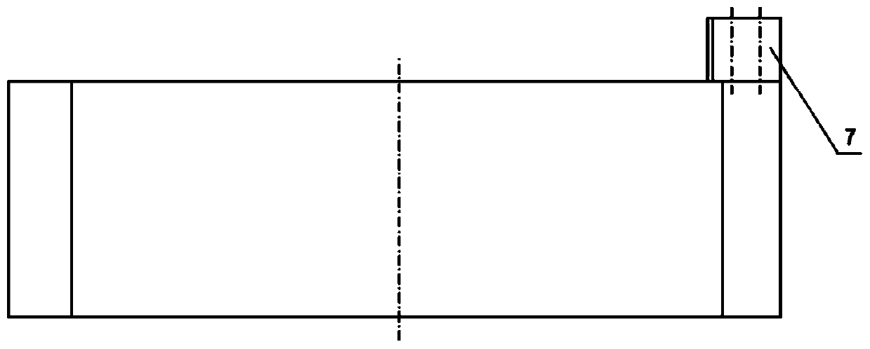
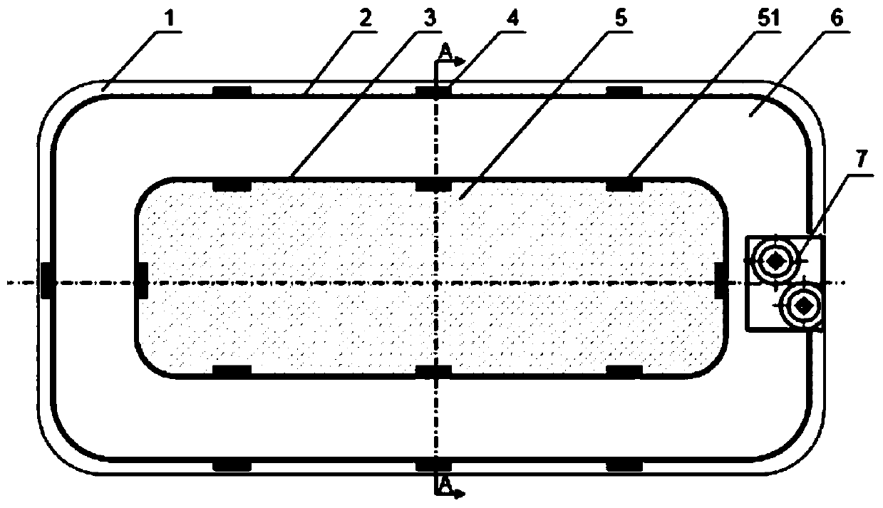
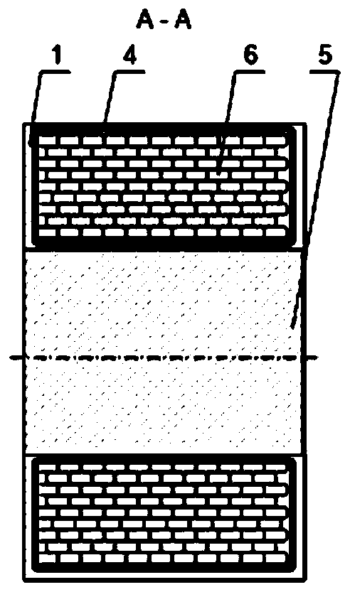
[0034] like Figure 1 to Figure 4 As shown, the magnetic pole structure of this embodiment is suitable for the braking magnetic pole structure of the linear eddy current braking device of the maglev train. The dimensions of the magnetic pole structure are: length 382.5mm, width 167mm, height 93.5mm. The brake pole mainly includes an iron core 5 , an insulating tape 3 , a coil 6 , a heat-shrinkable cable tie 4 , a glass fiber mesh 2 , an epoxy resin encapsulation layer 1 and a terminal post 7 .

[0035] Among them, the iron core 5 is made of low-carbon steel with good magnetic permeability and high strength, which is used to conduct the magnetic circuit and tra...


PUM


Abstract

The invention discloses a brake magnetic pole structure for a linear eddy current brake device. The transformer comprises an iron core, an insulating layer, a coil, a supporting layer, a fixing ribbon, a binding post and a packaging layer, a plurality of grooves in the axial direction are formed in the periphery of the iron core at intervals, the insulating layer wraps the periphery of the iron core, the fixing ribbon is fixed in the grooves of the iron core, and the coil is wound around the periphery of the insulating layer and used for generating magnetomotive force after being powered on; and the coil is tightened by the fixing ribbons, and the coil, the insulating layer and the supporting layer are fixed together and kept in the periphery of the iron core. According to the invention, the rectangular grooves in the periphery of the iron core are used for placing and fixing the ribbon, so that the aluminum flat wire has more winding space, the groove fullness rate is improved, and the ampere-turns number is increased. The number of ampere turns can be increased by 4%, the braking force can be increased by 0.4%, and the braking force caused by reduction of the sectional area of the iron core is reduced to 0.2%, so that the braking force is increased by 0.2%. The rated power of a brake magnetic pole is about 3.2 kW, the maximum magnetomotive force is 21.7 kA, and the requirements of a new generation of maglev train are met.

Description

technical field [0001] The invention belongs to the technical field of rail vehicle braking systems, and in particular relates to a braking magnetic pole structure suitable for maglev trains. Background technique [0002] Most existing maglev trains use linear eddy current braking devices for emergency braking. Linear eddy current braking technology uses the magnetic field generated by the braking magnetic pole under high-speed conditions to generate eddy currents on the side rails. According to Maxwell's law and Lenz's law, the magnetic field generated by the eddy current interacts with the original magnetic field to generate braking force. The power is finally transmitted to the vehicle bogie through the brake pole core, yoke and tie rod assembly to realize vehicle braking. [0003] The maximum speed of the Shanghai maglev train is 500km / h. The linear eddy current braking device used on the car uses magnetic poles, and the rated magnetomotive force of a single magnetic po...

Claims


Application Information

Patent Timeline
IPC IPC(8): H02K49/04B61H7/08
CPCB61H7/083B61H7/086H02K49/04
Inventor 张东升杨俊牛瑞朱新宇刘赛赛余毅权臧传相曹云丽
Owner NANJING CRRC PUZHEN HAITAI BRAKE EQUIP CO LTD
Learn More