Automatic assembly equipment for water valve
A technology for assembling equipment and water valves, which is applied in metal processing equipment, assembly machines, metal processing, etc., can solve the problems of large equipment footprint, complex assembly process, and prolonged assembly cycle, and achieve small footprint and high degree of automation High, short assembly cycle effect
- Summary
- Abstract
- Description
- Claims
- Application Information
AI Technical Summary
Problems solved by technology
Method used
Image

Examples
Embodiment 1
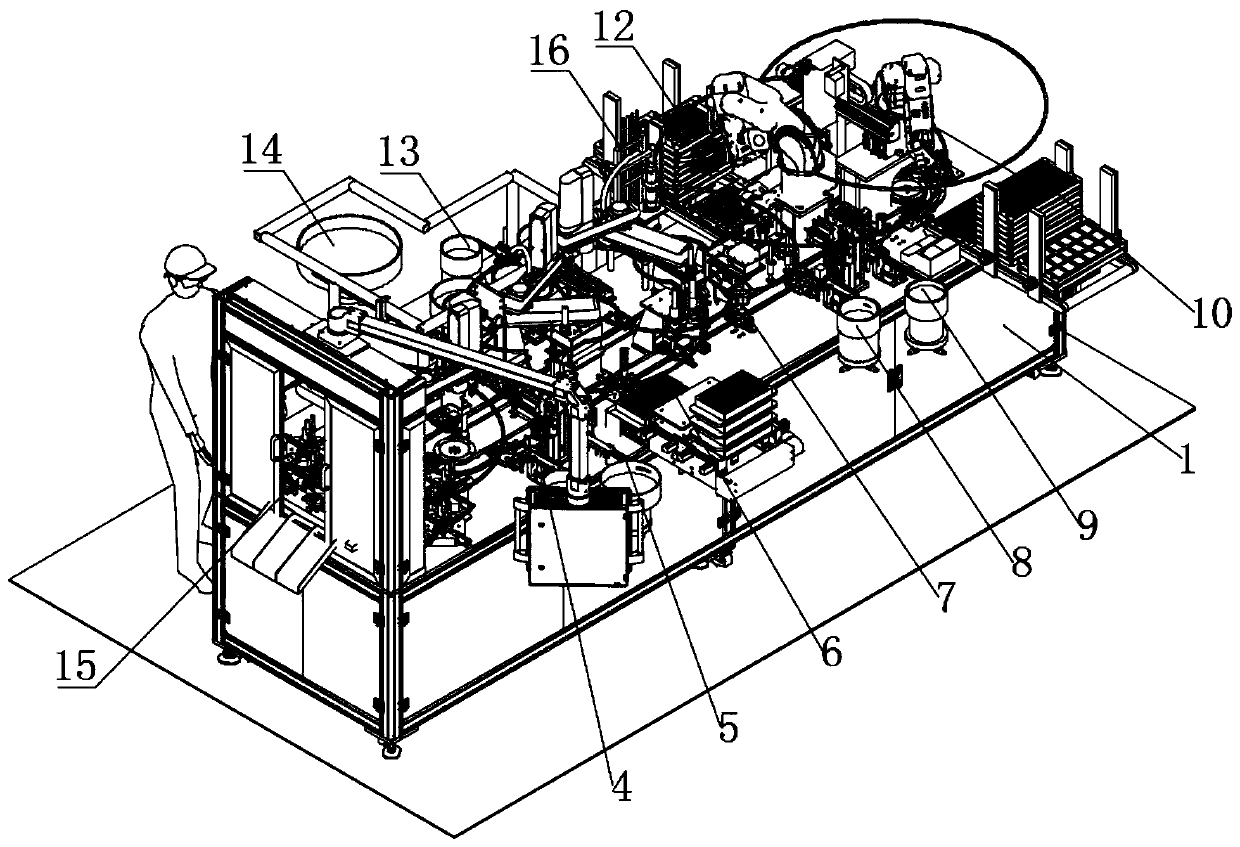
[0048] Please also see figure 1 and figure 2 , the present invention provides an automatic assembly equipment for water valves, which includes a box-type frame 1 and a water valve assembly line mechanism. The box-type frame 1 is provided with a track-shaped rotary conveyor 2 on which There is a positioning fixture 3 for disassembly and connection, and the positioning fixture 3 can be disassembled and replaced to adapt to the assembly of products of different specifications; the water valve assembly line mechanism includes several assembly stations, and several assembly stations are arranged in sequence along the rotary conveyor table 2 , the rotary conveyor table 2 drives the positioning fixture 3 to move and transport the water valve body to each station for assembly.
[0049] The entire water valve assembly assembly line mechanism is arranged around the rotary conveyor 2, which facilitates equipment installation. At the same time, this arrangement reduces the footprint of ...
Embodiment 2
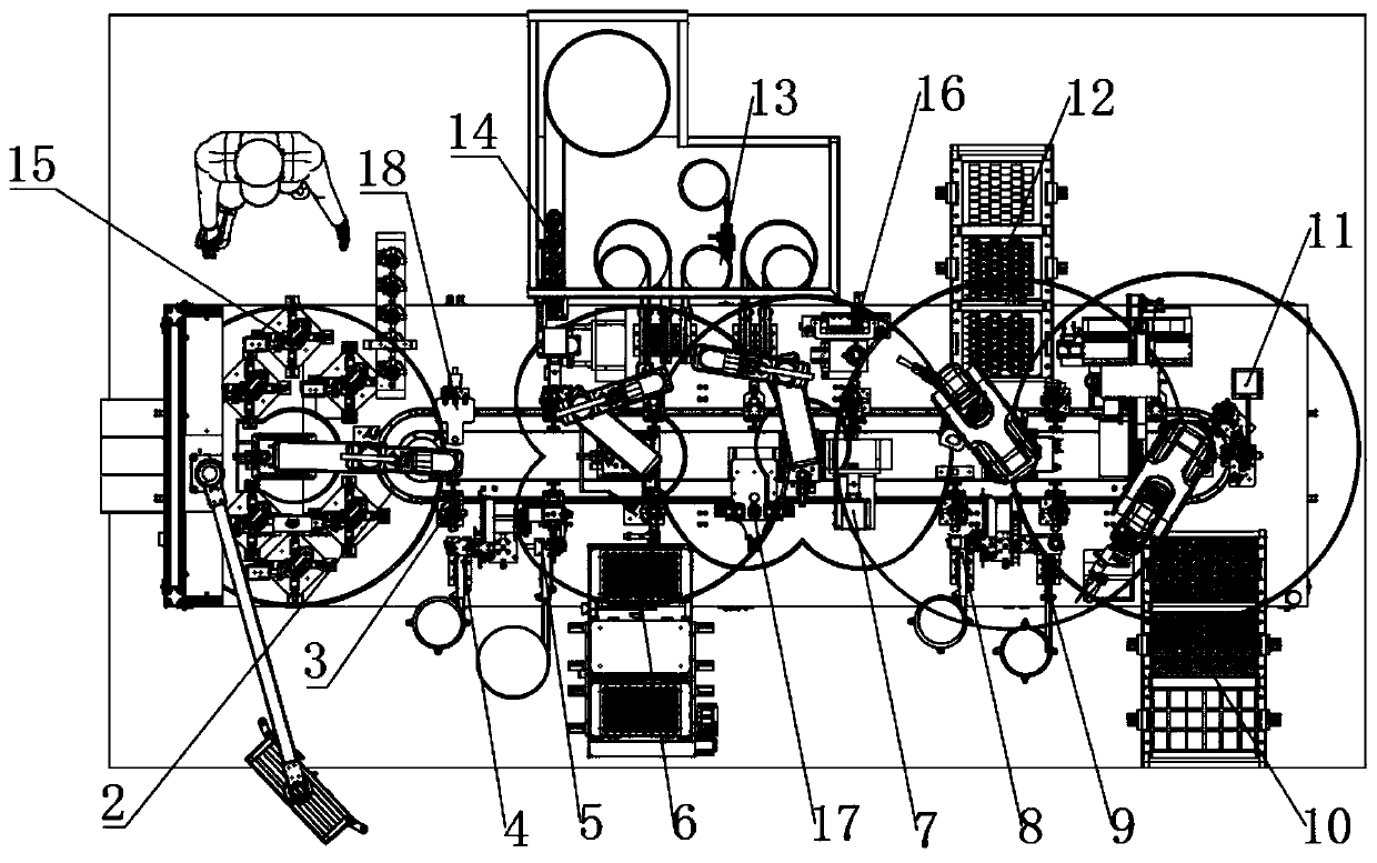
[0051] Please also see Figure 1-15 , On the basis of the first embodiment above, the water valve is assembled. The automatic assembly equipment of the water valve includes a box-type frame 1, on which a runway-shaped rotary conveyor 2 is arranged, and on the rotary conveyor 2 is fixed a Body) positioning jig 3, along the rotary conveyor table 2, the first seal ring assembly station 4, the side apron assembly station 5, the valve core assembly station 6, the round cover welding station 7, the second Seal ring assembly station 8, plug assembly station 9. Such as figure 1 and figure 2 As shown, the rotary conveyor 2 operates to transport the positioning jig 3 carrying the water valve body to each station for assembly.
Embodiment 3
[0053] Please also see Figure 1-15 , on the basis of the above-mentioned embodiment one, the difference from the above-mentioned embodiment two is that the electronic water valve is assembled, the automatic assembly equipment of the electronic water valve includes a box-type frame 1, and the box-type frame 1 is provided with The track-type rotary conveyor 2 is fixed with a positioning fixture 3 for clamping the electronic water valve body (that is, the housing of the electronic water valve), and the first sealing ring is sequentially arranged along the rotary conveyor 2 Assembly station 4, side apron assembly station 5, valve core assembly station 6, dome welding station 7, second sealing ring assembly station 8, plug assembly station 9, PCB board assembly station 10, Laser coding station 11, motor assembly station 12, gear assembly station 13, bottom cover welding station 14 and comprehensive performance testing station 15. Such as figure 1 and figure 2 As shown, the rot...
PUM
 Abstract
Description
Claims
Application Information
 - R&D
- Intellectual Property
- Life Sciences
- Materials
- Tech Scout
- Unparalleled Data Quality
- Higher Quality Content
- 60% Fewer Hallucinations
Browse by: Latest US Patents, China's latest patents, Technical Efficacy Thesaurus, Application Domain, Technology Topic, Popular Technical Reports.
© 2025 PatSnap. All rights reserved.Legal|Privacy policy|Modern Slavery Act Transparency Statement|Sitemap|About US| Contact US: help@patsnap.com