
Tamping machine

A technology of tamping machine and rubber pad, which is applied in the direction of roads, road repairs, roads, etc. It can solve the problems that large tamping machines cannot work normally, cannot provide sufficient tamping, and increase energy consumption of the device. Achieve the effect of easy realization, convenient replacement and cleaning, and speed up construction

Active Publication Date: 2020-07-31
CHINA NAT CHEM ENG THIRD CONSTR
View PDF6 Cites 2 Cited by
  • Summary
  • Abstract
  • Description
  • Claims
  • Application Information

AI Technical Summary

Problems solved by technology

[0004] At present, there are some narrow construction sites in some construction sites, which cause some common large tamping machines to not work normally, and when replaced with small tamping equipment, they cannot provide sufficient tamping. Therefore, At present, some construction sites will connect the tamping mechanism to the breaker of the excavator for tamping work.
[0005] However, most of the current tamping devices of this type use a steel plate directly welded on the breaker for tamping. speed will also be affected

Method used


Image

  • Tamping machine
  • Tamping machine
  • Tamping machine

Examples


Embodiment 1

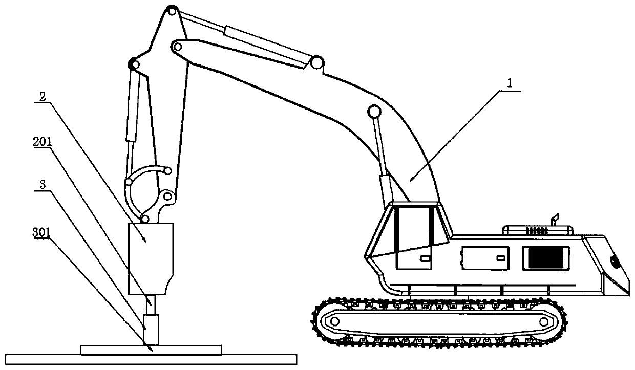
[0025] Such as Figure 1-3 As shown, a compacting machine includes an excavator 1 and a breaker 2. The output shaft 201 of the breaker 2 is slidably connected with a compacting mechanism 3, so that the output shaft 201 can continuously knock on the ground without driving the compacting mechanism 3. Hit the upper hammer plate 301 and enable the lower rammed earth plate 302 to continuously tamp the contacted ground, greatly reducing the output energy consumption of the breaking hammer 2, and speeding up the construction speed of the tamping operation;

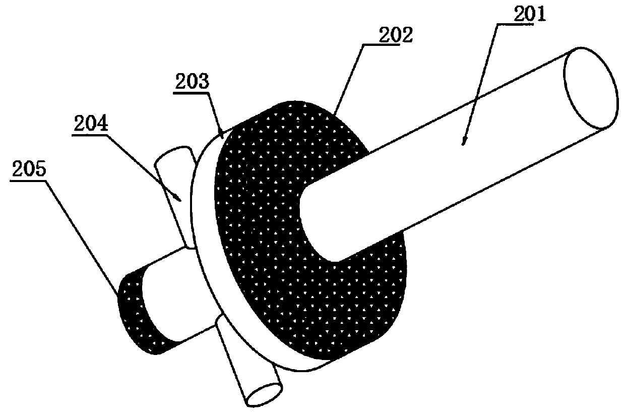
[0026] The output shaft 201 of the breaker 2 is provided with an anti-off plate 203, an upper rubber pad 202, several limit rods 204, and a lower rubber pad 205. Both the upper rubber pad 202 and the lower rubber pad 205 are used for buffering and vibration reduction. Effect, can prevent the deformation of the output shaft 201 and the tamping mechanism 3 caused by the impact, and can reduce the noise generated by the impact;

[...

Embodiment 2

[0030] Such as Figure 2-4 As shown, a compacting machine includes an excavator 1 and a breaker 2. The output shaft 201 of the breaker 2 is slidably connected with a compacting mechanism 3, so that the output shaft 201 can continuously knock on the ground without driving the compacting mechanism 3. Hit the upper hammer plate 301 and enable the lower rammed earth plate 302 to continuously tamp the contacted ground, greatly reducing the output energy consumption of the breaking hammer 2, and speeding up the construction speed of the tamping operation;

[0031] The output shaft 201 of the breaker 2 is provided with an anti-off plate 203, an upper rubber pad 202, several limit rods 204, and a lower rubber pad 205. Both the upper rubber pad 202 and the lower rubber pad 205 are used for buffering and vibration reduction. Effect, can prevent the deformation of the output shaft 201 and the tamping mechanism 3 caused by the impact, and can reduce the noise generated by the impact;

[...


PUM


Abstract

The invention relates to a tamping machine, which comprises an excavator and a breaking hammer, wherein an output shaft of the breaking hammer is connected with a tamping mechanism in a sliding manner, an anti-disengaging plate, an upper rubber mat, a plurality of limiting rods and a lower rubber mat are arranged on the output shaft of the breaking hammer, the tamping mechanism comprises an upperhammer plate, a lower earth tamping plate welded to the lower end of the upper hammer plate, a connecting column welded to the upper end of the upper hammer plate and sliding grooves formed in the inner wall of the connecting column, the anti-disengaging plate, the upper rubber mat, the plurality of limiting rods and the lower rubber mat are all located in the connecting column, the limiting rodsare located in the sliding grooves, the diameter of the anti-disengaging plate is the same as that of the upper rubber mat, a gap is formed between the anti-disengaging plate and the connecting column, the upper rubber mat is connected to the upper end surface of the anti-disengaging plate, and the lower rubber mat is connected to the lower end surface of the output shaft. The tamping machine canwork in various environments, the whole earth tamping mechanism cannot be lifted when the output end of the breaking hammer is lifted in the working process, the working energy consumption of the breaking hammer is greatly reduced, and the earth tamping speed is increased.

Description

technical field [0001] The invention belongs to the field of civil engineering construction, and in particular relates to a compacting machine with high efficiency and low consumption. Background technique [0002] The vibrating plate tamping machine is a tamping machine that tamps the road surface through the vibration of the vibrating plate. Mainly through the dynamic action inside the machine, the layer to be rolled is permanently deformed and compacted, which is suitable for various compaction operations. [0003] Excavator-type vibrating plate tamping machine The vibrating plate tamping machine consists of three parts: vibrating plate, power unit, and connecting device. The vibration plate is the part that is in contact with the ground and is compacted. The power unit refers to the internal vibration motor, which vibrates through hydraulic pressure and transmits it to the vibrating plate for compaction. The vibrating plate compacting machine is generally connected wi...

Claims


Application Information

Patent Timeline
Patent Type & Authority Applications(China)
IPC IPC(8): E01C19/34E01C19/38
CPCE01C19/34E01C19/38
Inventor 赵晓磊
Owner CHINA NAT CHEM ENG THIRD CONSTR
Learn More