
A traction device for post-processing of aluminum alloy extrusion

A kind of traction equipment and aluminum alloy technology, which is applied in the field of post-processing of aluminum alloy extrusion, can solve the problems such as the inability to adjust the traction direction, easy splashing of aluminum chips, and injury to the staff, so as to ensure the production environment, easy to use, and improve work efficiency Effect

Active Publication Date: 2020-12-08
盐城金圣汽车部件有限公司
View PDF5 Cites 0 Cited by
  • Summary
  • Abstract
  • Description
  • Claims
  • Application Information

AI Technical Summary

Problems solved by technology

[0002] The aluminum alloy profile has a long strip structure. In the production process, it is mainly produced by extrusion molding. Since it is produced by molding after high temperature melting, in order to facilitate the transmission of aluminum profiles along the production line, in the prior art, the transmission Traction equipment is installed on the side of the device. When discharging, the traditional operation method is that the staff needs to manually pull it. After reaching the specified length, it is cut by the cutting machine at the discharge port.
This manual traction method has low work efficiency, and manual traction is likely to cause injuries to workers. In addition, some existing aluminum profile tractors have complicated structures, and when the aluminum alloy is discharged from the discharge port of the extruder When cutting the material, it is easy to form a curved shape, and the existing tractor cannot adjust the traction direction according to the discharge situation, and when the existing aluminum alloy profile is cut, the aluminum chips are easy to splash out, which is not conducive to collection

Method used


Image

  • A traction device for post-processing of aluminum alloy extrusion
  • A traction device for post-processing of aluminum alloy extrusion
  • A traction device for post-processing of aluminum alloy extrusion

Examples


Embodiment Construction

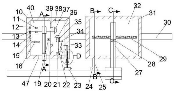
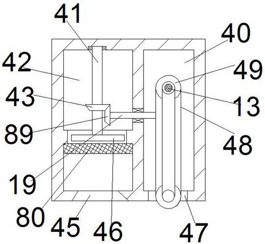
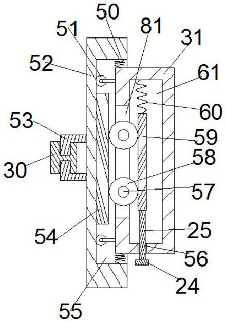
[0017] Combine below Figure 1-5 The present invention is described in detail, and for convenience of description, the orientations mentioned below are now stipulated as follows: figure 1 The up, down, left, right, front and back directions of the projection relationship itself are the same.

[0018] refer to Figure 1-5 , according to an embodiment of the present invention, a traction device for extruded aluminum alloys includes a left body 10 and a right body 31, a power chamber 38 is provided in the left body 10, and a power chamber 38 is provided in the power chamber 38. There is a power device, a transmission chamber 40 is provided in the left body 10, a transmission device is provided in the transmission chamber 40, an absorption chamber 42 is provided in the left body 10, an absorption device is provided in the absorption chamber 42, The right body 31 is provided with a clamping cavity 44, the clamping cavity 44 is provided with a clamping device, the left body 10 and...


PUM


Abstract

The invention discloses a traction device for aluminum alloy extrusion post-processing. The traction device comprises a left body and a right body, a power cavity is arranged in the left body, a powerdevice is arranged in the power cavity, a transmission cavity is arranged in the left body, a transmission device is arranged in the transmission cavity, an absorption cavity is arranged in the leftbody, an absorption device is arranged in the absorption cavity, a clamping cavity is arranged in the right body, a clamping device is arranged in the clamping cavity, the left body and the right bodyare provided with alignment devices, and the right body is provided with an adjusting device. The traction device is simple in mechanism and simple and convenient in use; by arranging the clamping device, rapid clamping of aluminum alloy profiles can be achieved without manual traction, so that the working efficiency is improved, and the safety of workers is guaranteed; by arranging the adjustingdevice, the traction direction can be adjusted automatically, the problem of bending of the aluminum alloy profiles during traction is solved, the scrap rate of products is reduced; and meanwhile, byarranging the absorption device, cut aluminum scraps can be collected, and the production environment of the workshop is guaranteed.

Description

technical field [0001] The invention relates to the technical field of post-processing of aluminum alloy extrusion, in particular to a traction device for post-processing of aluminum alloy extrusion. Background technique [0002] The aluminum alloy profile has a long strip structure. In the production process, it is mainly produced by extrusion molding. Since it is produced by molding after high temperature melting, in order to facilitate the transmission of aluminum profiles along the production line, in the prior art, the transmission Traction equipment is installed on the side of the device. When discharging, the traditional operation method is that the staff needs to manually pull it. After reaching the specified length, it is cut off by the cutting machine at the discharge port. This manual traction method has low working efficiency, and manual traction is likely to cause injuries to workers. In addition, some existing aluminum profile tractors have complicated structur...

Claims


Application Information

Patent Timeline
Patent Type & Authority Patents(China)
IPC IPC(8): B21C35/02
CPCB21C35/02
Inventor 徐丹
Owner 盐城金圣汽车部件有限公司
Learn More