
Wear-resistant pump body and manufacturing method thereof

A wear-resistant pump and wear-resistant layer technology, which is applied in the manufacture of tools, pumps, pump components, etc., can solve the problems of difficult lining forming, large kiln space, and high manufacturing cost, and achieve less assembly work and reduced overall length , the effect of good wear resistance

Pending Publication Date: 2020-07-28
GUANGZHOU TOTALL MATERIAL TECH CO LTD
View PDF2 Cites 1 Cited by
  • Summary
  • Abstract
  • Description
  • Claims
  • Application Information

AI Technical Summary

Problems solved by technology

The invention overcomes the difficulty in forming the inner lining of the pump body, the disadvantages of large kiln space, low yield, and high manufacturing cost during sintering due to the excessively large external dimensions, and divides the inner lining into curved parts with an area and shape suitable for casting. panel, which can greatly reduce the difficulty of forming and improve the yield of sintering

Method used


Image

  • Wear-resistant pump body and manufacturing method thereof
  • Wear-resistant pump body and manufacturing method thereof
  • Wear-resistant pump body and manufacturing method thereof

Examples


Embodiment 1

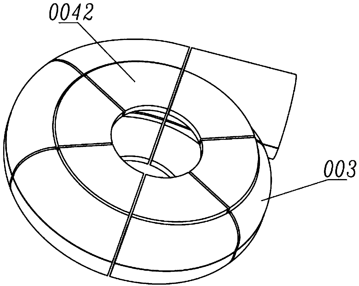
[0061] like figure 1 , 2 , 3, Embodiment 1 of the present invention is a wear-resistant pump body of a medium-sized pump. The wear-resistant pump body includes a metal shell and a ceramic lining, wherein the metal shell includes a front shell 001 and a rear shell 005, and the water inlet 008 is arranged at On the front shell 001, the front shell 001 and the rear shell 005 are buckled on a plane A-A passing through the water outlet and connected together by bolts 009. The ceramic lining includes 12 pieces of different shapes arranged on the axial side of the wear-resistant pump body, sequentially The combined curved plate 003 also includes a fan-shaped front annular plate 0041 arranged on the side of the feed port of the wear-resistant pump body and a rear annular plate 0042 arranged on the other side. The front annular plate and the rear annular plate are respectively made of 6 fan-shaped boards are put together; such as image 3 Shown is a schematic diagram of the rear rin...

Embodiment 2

[0063] like Figure 4 As shown, Embodiment 2 of the present invention is a three-dimensional view after the curved panels of a large wear-resistant pump body are assembled, including 40 curved panels 003 of silicon nitride and silicon carbide, and the working surface area of ​​a single curved panel is 0.1- 0.15 square meters, the axial projection angle of a single curved panel is 15°-20°, and the inner contour of all the curved panels 003 is two circles.

Embodiment 3

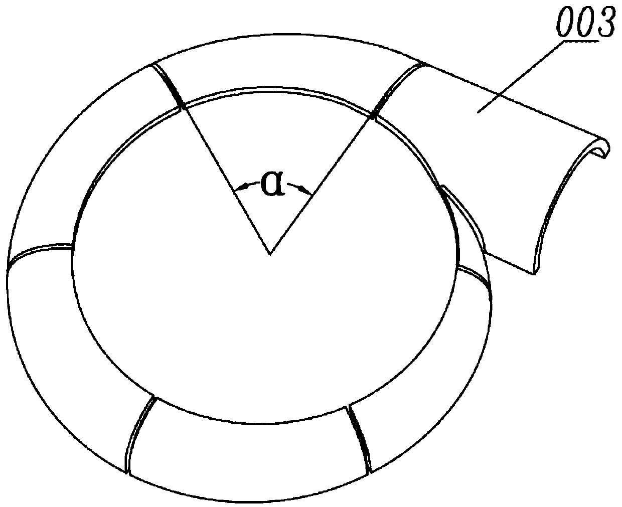
[0065] Embodiment 3 of the present invention is a medium-sized wear-resistant pump body, Figure 5 Shown is one of the curved panels 003, a plane 0032 coincident with the A-A plane is provided on the curved panel 003, and a protruding lip 0031 extending outward along the A-A plane is also provided to enhance the wear resistance of the place. The area of ​​the curved panel is 0.13m 2 , the axial projection angle α is 62°.


PUM


Abstract

The invention discloses a wear-resistant pump body and a manufacturing method thereof. The wear-resistant pump body comprises a shell and a lining arranged on the inner side of the shell, wherein a water inlet is formed in one side of the shell, the shell is provided with an A-A plane and a water outlet, the shell comprises a front shell and a rear shell which are detachably connected along the A-A plane, the lining comprises a plurality of curved plates which can be spliced in sequence, the lining further comprises a front annular plate arranged on one side close to the water inlet and a rearannular plate arranged on the other side, and a buffer wear-resistant layer is further arranged between the shell and the lining. The wear-resistant pump body has the advantages that the manufacturing cost of a wear-resistant pump can be remarkably reduced by selecting a reasonable splicing mode of a ceramic lining and the reasonable shape and boundary dimension of the curved plates, the coarse particle scouring resistance of the wear-resistant pump body is improved, the service life of the pump body is prolonged, the reliability of the pump body is improved, and the large-scale production iseasy to realize.

Description

technical field [0001] The invention relates to rotary power pump equipment, in particular to a wear-resistant pump body and a manufacturing method thereof. Background technique [0002] In industries such as mineral processing and smelting, centrifugal pumps are often used to transport some abrasive solid-liquid two-phase flows, and wear-resistant pumps are often used. The flow parts of the wear-resistant pump are severely worn, and the wear-resistant pump body is one of the most worn parts. In order to improve the life of the wear-resistant pump, the pump body must be made of wear-resistant materials. The most commonly used wear-resistant materials are wear-resistant Alloy and rubber, but the properties of these two wear-resistant materials often cannot meet the requirements of many working conditions. [0003] In recent years, some technologies of using ceramic materials to manufacture wear-resistant pump bodies have been disclosed, such as CN108425850A. This technology ...

Claims


Application Information

Patent Timeline
Patent Type & Authority Applications(China)
IPC IPC(8): F04D29/42F04D29/02B28B1/14
CPCB28B1/14F04D29/026F04D29/426F04D29/4286
Inventor 肖琼
Owner GUANGZHOU TOTALL MATERIAL TECH CO LTD
Learn More