Rolling bearing arrangement

A bearing device and rolling bearing technology, applied in the field of bearing devices, can solve problems such as wear and tear, and achieve the effect of small unit area pressure

Pending Publication Date: 2020-07-24
THYSSENKRUPP ROTHE ERDE +1
View PDF16 Cites 3 Cited by
  • Summary
  • Abstract
  • Description
  • Claims
  • Application Information

AI Technical Summary

Problems solved by technology

In addition, the use of toroidal roller bearings as non-locating bearings results in only a limited ability to accommodate axial movements of the shaft, eg due to thermal expansion
Another disadvantage is that, in toroidal roller bearings, the radius of curvature of the convex spherical rolling elements is smaller than that of the raceways, so that such bearings have an increased ease of sliding, which can lead to serious problems especially under high loads wear and tear

Method used


Image

  • Rolling bearing arrangement
  • Rolling bearing arrangement

Examples


Embodiment Construction

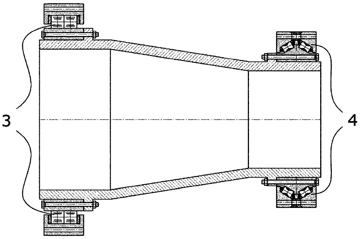
[0025] figure 1 is a schematic radial cross-sectional view of a bearing arrangement of a rotor shaft of a wind power plant according to a possible embodiment of the present invention. In wind power plants, the hub is connected to the generator via the rotor shaft, whereby the rotation of the hub is transmitted to the generator and converted there into electrical energy. Here, according to the invention, the shaft is rotatably mounted by means of two rolling bearing arrangements 3 and 4 . Depending on their position relative to the hub and generator, the two rolling bearing arrangements 3 and 4 are referred to as hub-side bearing 3 and generator-side bearing 4 . The hub side corresponds to the left side in the figure, and the generator side corresponds to the right side.

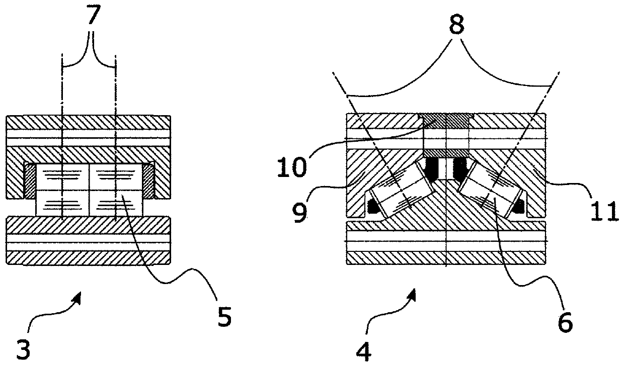
[0026] In this embodiment, the hub-side bearing 3 is formed by two rows of cylindrical rollers 5 which roll between two bearing rings in rotation. The cylindrical rolling bodies transmit the forces between...


PUM


Abstract

The invention relates to a bearing arrangement for a rotor shaft of a wind power plant, in which the rotor shaft transmits a rotation of a hub provided with rotor blades to a generator, wherein the bearing arrangement comprises a hub-side rolling bearing and a generator-side rolling bearing, wherein the hub-side rolling bearing bearing (3) is designed as a multi-row radial roller bearing, and thegenerator-side rolling bearing (4) is designed as a tapered roller bearing.

Description

technical field [0001] The invention relates to a bearing arrangement for a rotor shaft of a wind power plant, wherein the rotor shaft transmits the rotation of a hub with rotor blades to a generator, wherein the bearing arrangement comprises a hub-side rolling bearing and a generator-side rolling bearing. Background technique [0002] During operation, the rotor shaft of a wind power plant transmits the rotation of the rotor blades to the generator, where the rotation of the rotor driven by the flowing air is converted into electrical energy. The rotor shaft can be supported in different ways in the nacelle of the wind power plant. According to a first bearing concept, two bearing points spaced apart from one another in the axial direction of the rotor shaft are provided, wherein a floating bearing is arranged on one bearing point and a fixed bearing is arranged on the other bearing point (fixed / floating bearing) . According to a second bearing variant, the hub is screwed...

Claims


Application Information

Patent Timeline
Patent Type & Authority Applications(China)
IPC IPC(8): F16C19/28F16C19/36F16C19/38F16C33/64F16C19/54F16C33/52F16C33/48F03D80/70
CPCF16C19/28F16C19/385F16C33/48F16C33/523F16C33/64F16C19/546F03D80/70F16C2360/31F05B2240/50F05B2240/60Y02E10/72F16C2300/14
Inventor 斯蒂芬·弗罗宁简-彼得·博赫特
Owner THYSSENKRUPP ROTHE ERDE
Why Eureka
Try Eureka