
Drive circuit and display device

一种驱动电路、显示装置的技术,应用在静态指示器、数字存储器信息、仪器等方向,能够解决上拉单元电性能影响、薄膜晶体管源漏极蚀刻不均等问题,达到避免电性受影响的效果

Active Publication Date: 2020-07-24
SHENZHEN CHINA STAR OPTOELECTRONICS SEMICON DISPLAY TECH CO LTD
View PDF8 Cites 0 Cited by
  • Summary
  • Abstract
  • Description
  • Claims
  • Application Information

AI Technical Summary

Problems solved by technology

[0004] The purpose of this application is to provide a driving circuit and a display device to solve the problem that the electrical performance of the pull-up unit is affected by uneven etching of the source and drain of the thin film transistor connected to the bootstrap capacitor in the pull-up unit of the gate drive circuit. question

Method used


Image

  • Drive circuit and display device
  • Drive circuit and display device
  • Drive circuit and display device

Examples


Embodiment Construction

[0026] The technical solutions in the embodiments of the present application will be clearly and completely described below in conjunction with the drawings in the embodiments of the present application. Apparently, the described embodiments are only some of the embodiments of this application, not all of them. Based on the embodiments in this application, all other embodiments obtained by those skilled in the art without making creative efforts belong to the scope of protection of this application.

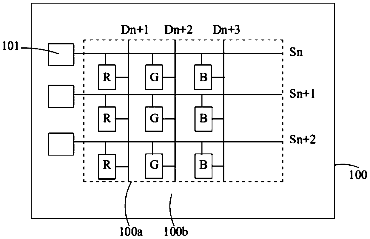
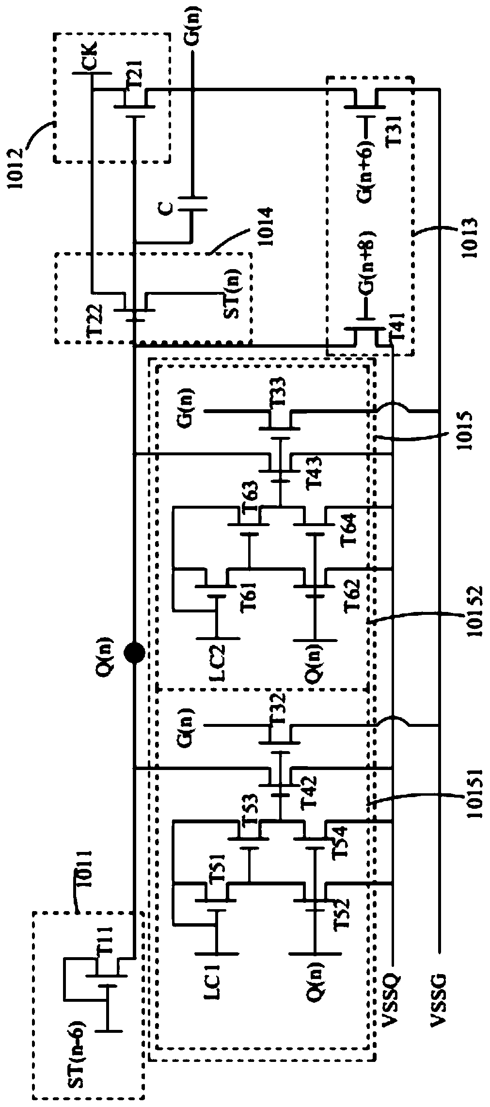
[0027] see Figure 2-Figure 4 , figure 2 is a schematic diagram of a display device in an embodiment of the present application, image 3 for figure 2 The schematic diagram of the driving circuit in the shown display device, Figure 4 for image 3 A schematic plan view of the pull-up unit and the bootstrap capacitor of the middle gate drive circuit.

[0028] The display device includes a display panel 100 having a display area 100a and a non-display area 100b located on t...


PUM


Abstract

The invention provides a drive circuit and a display device, the drive circuit comprises a circuit unit, the circuit unit comprises a thin film transistor, and the thin film transistor comprises a patterning part; the capacitor is connected with at least one end of the thin film transistor in the circuit unit, and the capacitor comprises an electrode plate; and a redundant patterning part, the redundant patterning part, the electrode plate and the patterning part are located on the same conductive layer, and the redundant patterning part is connected between the patterning part and the electrode plate. The redundant patterning component is arranged between the patterning component forming the thin film transistor and the electrode plate of the capacitor, so that the problem that the electrical property of the thin film transistor of the circuit unit is affected due to uneven etching of the patterning component of the thin film transistor in the process of patterning the conductive layer is avoided.

Description

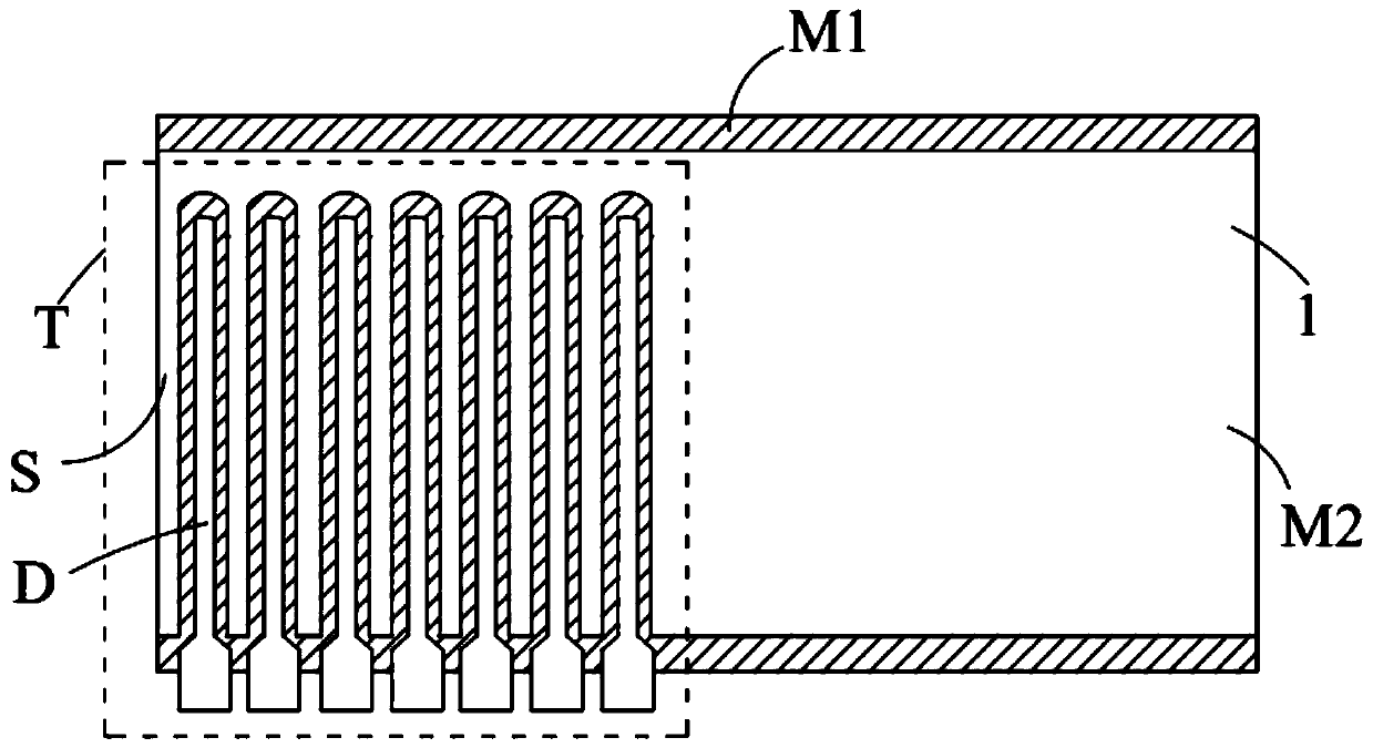
technical field [0001] The present application relates to the field of display technology, in particular to a driving circuit and a display device. Background technique [0002] Such as figure 1 As shown in FIG. 2 , it is a schematic plan view of the connection between the pull-up unit T and the bootstrap capacitor of a conventional gate drive circuit (Gate On Array, GOA). The pull-up unit T includes a plurality of thin film transistors arranged in an array and connected in series, each thin film transistor includes a gate, a source and a drain, and the bootstrap capacitor includes a first electrode and a second electrode. The gates of the thin film transistors arranged in multiple arrays and the first electrodes of the bootstrap capacitors are located on the entire first metal layer M1, and the sources and drains (S, D) of the thin film transistors and the bootstrap capacitors are arranged in multiple arrays. The second electrode 1 is located on the patterned second metal...

Claims


Application Information

Patent Timeline
Patent Type & Authority Applications(China)
IPC IPC(8): G09G3/20
CPCG09G3/20G09G2310/0286G09G3/3266G11C19/28G09G2300/0408G09G2300/0413G09G2300/0426G09G2300/0876
Inventor 高雅楠彭邦银金一坤
Owner SHENZHEN CHINA STAR OPTOELECTRONICS SEMICON DISPLAY TECH CO LTD
Learn More