
Puncture angle adjusting device and puncture assisting robot

A technology for adjusting device and puncture angle, applied in the field of medical equipment, can solve the problems of large error, large size, low transmission efficiency, etc., and achieve the effects of low cost, long life and fast installation

Active Publication Date: 2020-07-21
BEIJING INSTITUTE OF TECHNOLOGYGY
View PDF5 Cites 2 Cited by
  • Summary
  • Abstract
  • Description
  • Claims
  • Application Information

AI Technical Summary

Problems solved by technology

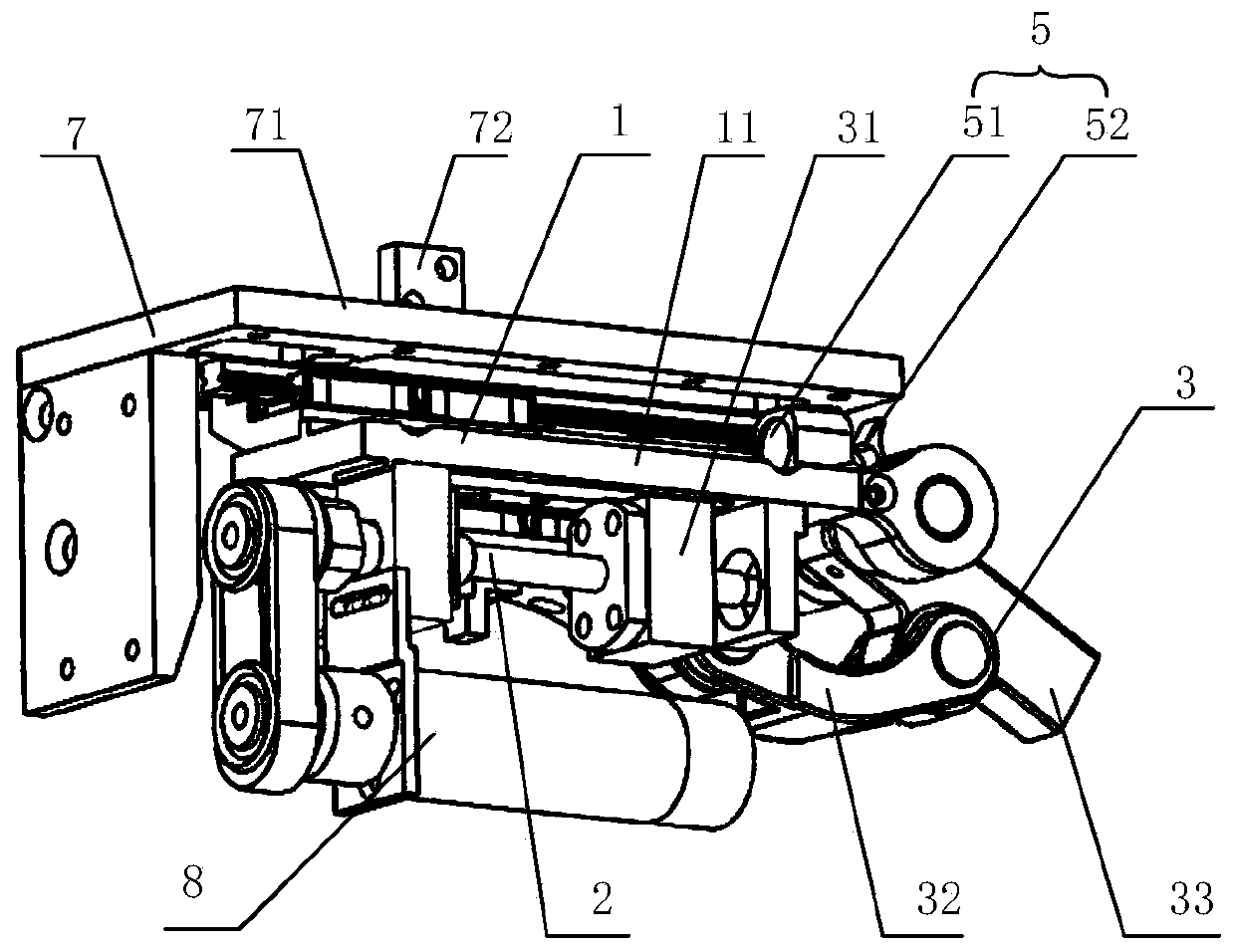
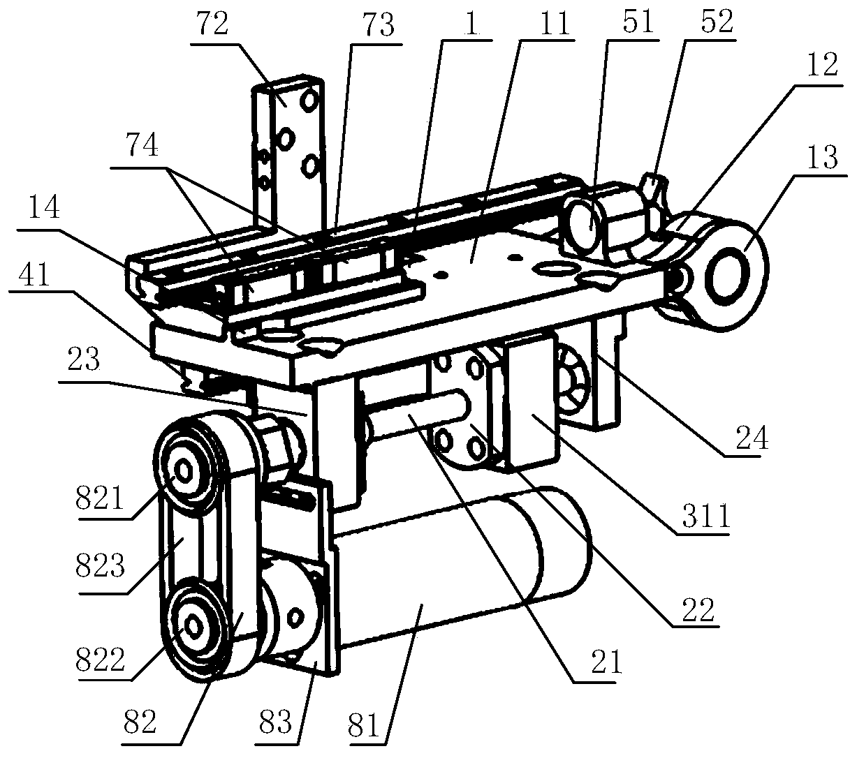
[0005] The purpose of the present invention is to provide a puncture angle adjustment device with high transmission efficiency and compact structure to solve the problems of low transmission efficiency, large error and large size of the existing puncture angle adjustment device

Method used


Image

  • Puncture angle adjusting device and puncture assisting robot
  • Puncture angle adjusting device and puncture assisting robot
  • Puncture angle adjusting device and puncture assisting robot

Examples


Embodiment Construction

[0045] In order to make the purpose, technical solution and advantages of the invention clearer, the technical solution in the invention will be clearly described below in conjunction with the drawings and specific embodiments. Apparently, the described embodiments are some of the embodiments of the invention, but not all of them. Based on the embodiments of the invention, all other embodiments obtained by persons of ordinary skill in the art without making creative efforts belong to the protection scope of the invention.

[0046] In the description of the present invention, it should be noted that, unless otherwise clearly specified and limited, the terms "first", "second", "third" and so on are for the purpose of clearly illustrating the numbering of product parts, and do not represent any substantive gender distinction. "Up", "Down", "Front", "Back", "Left" and "Right" are all subject to the directions shown in the attached drawings. "Front end", "back end" and "top" are ...


PUM


Abstract

The invention relates to the technical field of medical instruments, and discloses a puncture angle adjusting device and a puncture auxiliary robot, the puncture angle adjusting device comprises a base, and a lead screw mechanism and a connecting rod mechanism arranged on the base; the lead screw mechanism comprises a lead screw and a nut arranged on the lead screw in a sleeving mode. The lead screw is rotationally arranged on the base around the axis of the lead screw so as to drive the nut to do linear motion along the axis of the lead screw. The connecting rod mechanism comprises a transmission connecting block, a push rod and a rotating rod, one side of the transmission connecting block is connected to the nut, and the other side of the transmission connecting block is rotationally connected to one end of the push rod; the other end of the push rod is rotationally connected to the first connecting end of the rotary rod, the second connecting end of the rotary rod is rotationally connected to the base, and the third connecting end of the rotary rod is used for being connected with a puncture needle assembly. The puncture angle adjusting device can achieve continuous adjustment of the puncture angle by arranging the lead screw mechanism and the connecting rod mechanism, and has the advantages of being high in angle adjusting precision, long in service life, compact in structure and small in size.

Description

technical field [0001] The invention relates to the technical field of medical devices, in particular to a puncturing angle adjusting device and a puncturing assistant robot. Background technique [0002] Ultrasound-guided vascular puncture is widely used in diagnostic and auxiliary operations that require long-term injection of drugs, blood or nutrient solutions, as well as hemodynamic monitoring and venous pressure monitoring. Since the puncture operation requires high skill levels of medical staff, the success rate of puncture mainly depends on the level of medical skills of doctors, and the success rate of initial puncture is low, and the puncture angle of the puncture bracket used in puncture surgery is generally set to a fixed number of angles. To achieve a wide range of continuous adjustment. An existing infrared-guided ultrasonic positioning venipuncture system includes an ultrasonic positioning unit, a base, and a support rod arranged on the base. The ultrasonic po...

Claims


Application Information

Patent Timeline
IPC IPC(8): A61B17/34A61B34/30A61B34/20
CPCA61B17/3403A61B2017/3413A61B34/20A61B34/30A61B2034/2063A61B2034/2065
Inventor 张博张磊张立群张哲明黄强藤江正克
Owner BEIJING INSTITUTE OF TECHNOLOGYGY
Learn More