
Switch ringing suppression circuit based on gate driver and control method thereof

A technology for suppressing circuits and driving circuits, applied in control/regulation systems, instruments, electrical components, etc., can solve problems such as increasing additional losses, reducing converter efficiency, and power device heating, avoiding power loss and reducing costs. Effect

Pending Publication Date: 2020-07-17
DALIAN UNIV OF TECH
View PDF0 Cites 1 Cited by
  • Summary
  • Abstract
  • Description
  • Claims
  • Application Information

AI Technical Summary

Problems solved by technology

However, if the capacitance of the RLC absorption circuit is too large, it will cause the power device to heat up and cause thermal breakdown. If the capacitance is too small, the absorption capacity for ringing is insufficient.
Compact line layout can reduce the parasitic inductance of the bus, but it will also cause heat accumulation of the converter under long-term operation
Adding resistance in the drive loop slows down the rise time of the signal, resulting in an increase in the dead time of the half-bridge circuit, increasing additional losses, and reducing the efficiency of the converter
In addition, the above three methods require custom design for each different power transistor, increasing development cost and design time

Method used


Image

  • Switch ringing suppression circuit based on gate driver and control method thereof
  • Switch ringing suppression circuit based on gate driver and control method thereof
  • Switch ringing suppression circuit based on gate driver and control method thereof

Examples


Embodiment Construction

[0029] The implementation method of the present invention will be described in detail below in conjunction with the accompanying drawings.

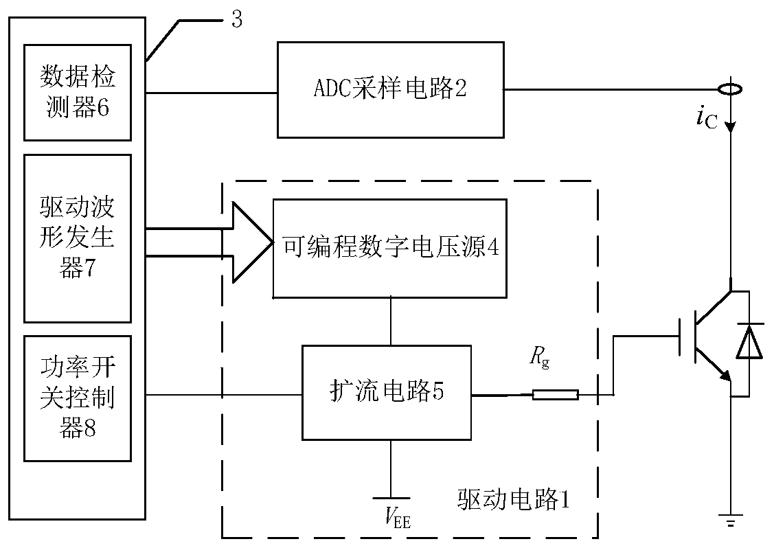
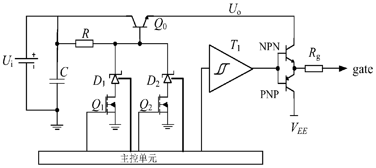
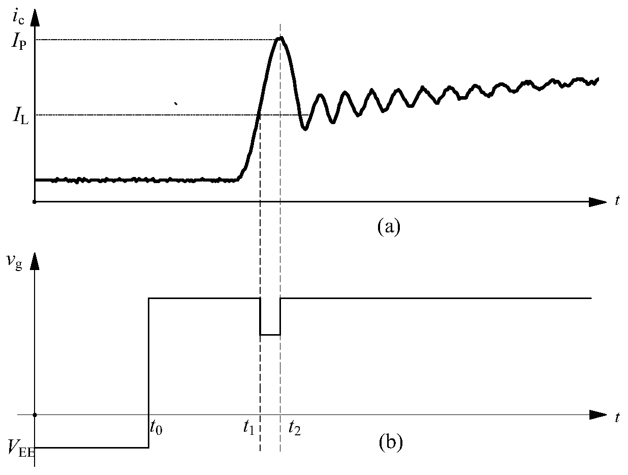
[0030] figure 1 It is a block diagram of the switch ringing suppression circuit of the present invention. figure 2 It is a schematic diagram of the driving circuit of the present invention. image 3 It is a schematic diagram of the output drive waveform obtained based on the current signal in the present invention. Figure 4 It is a flow chart of the switch ringing suppression control method of the present invention. Figure 5 It is the current waveform diagram before and after the ringing suppression in the embodiment of the present invention.

[0031] figure 1 The switch ringing suppression circuit block diagram includes a drive circuit 1, an ADC sampling circuit 2, and a main control unit 3, wherein the drive circuit 1 includes a programmable digital voltage source 4 and a current expansion circuit 5, and the main control unit 3 inc...


PUM


Abstract

The invention discloses a switch ringing suppression circuit based on a gate driver and a control method thereof, and belongs to the field of power electronic devices and control. The circuit comprises a driving circuit, an ADC sampling circuit and a main control unit, wherein the driving circuit comprises a programmable digital voltage source and a current expanding circuit, and the main controlunit comprises a data detector, a driving waveform generator and a power switch controller. A driving waveform generator in the main control unit outputs signals and transmits the signals to the programmable digital voltage source, the power switch controller outputs signals and transmits the signals to the current expanding circuit, and the data detector receives and processes the data sent by the sampling circuit. The sampling circuit measures the current flowing through the measured power switch tube and is connected with the collector / drain of the measured power switch tube. According to the invention, the ringing phenomenon of the power switch tube is suppressed by adjusting the driving waveform, and for different types of power switch tubes or different load conditions, the voltage value of ringing suppression only needs to be adjusted through a program. The ringing phenomenon is suppressed without changing the structure of the converter, and the reliability of the converter is improved.

Description

technical field [0001] The invention relates to a switch ringing suppression circuit based on a gate driver and a control method thereof, belonging to the field of power electronic devices and control. Background technique [0002] The dominant position in the power electronic converter is the voltage-type converter, which is characterized by the constant voltage polarity of the DC side and the bidirectional conduction of the current. The voltage-type converter usually uses an asymmetric turn-off power device and a diode of the same capacity in antiparallel connection to form the switching valve of the converter. The reverse recovery characteristics of the diode and the parasitic parameters in the converter circuit will cause The ringing phenomenon produces electromagnetic interference problems, affects high-speed signals in equipment, and seriously reduces the reliability of power devices and converters. [0003] The essence of the ringing phenomenon is a damped oscillatio...

Claims


Application Information

Patent Timeline
IPC IPC(8): H02M1/44H02M1/32H02M3/156H02M1/088
CPCH02M1/44H02M1/32H02M3/156H02M1/088H02M1/0038Y02B70/10
Inventor 王志强李琛吉兵
Owner DALIAN UNIV OF TECH
Learn More