Eureka AIR delivers breakthrough ideas for toughest innovation challenges, trusted by R&D personnel around the world.

A low voltage welding transformer

A welding transformer and low-voltage technology, applied in the field of transformers, can solve the problems of difficulty in heat dissipation of transformers, reduce the protection effect of transformers, and difficult to use transformers, and achieve the effects of increasing stability, increasing stability, and improving stability.

Active Publication Date: 2021-08-17
湖北金力特电气有限公司
View PDF3 Cites 0 Cited by
  • Summary
  • Abstract
  • Description
  • Claims
  • Application Information

AI Technical Summary

Problems solved by technology

[0002] The transformer is a device that uses the principle of electromagnetic induction to change the AC voltage. The main components are the primary coil, the secondary coil and the iron core (magnetic core). The main functions are: voltage conversion, current conversion, impedance conversion, isolation, voltage stabilization (magnetic Saturated transformer), etc., a transformer is a device that transforms AC voltage, alternating current, and impedance. When an AC current passes through the primary coil, an AC magnetic flux is generated in the iron core (or magnetic core), which induces a magnetic flux in the secondary coil. Voltage (or current), low-voltage welding transformer is a kind of transformer; the traditional outdoor installation transformer in the working process, the transformer generates a lot of heat and it is difficult to dissipate heat, the high temperature is difficult to avoid affecting the operation of the transformer, and it is difficult to wash the transformer loss in rainy days Use it to reduce the protective effect of the transformer

Method used


Image

  • A low voltage welding transformer
  • A low voltage welding transformer
  • A low voltage welding transformer

Examples


Embodiment Construction

[0019] Attached below Figure 1-4 The specific implementation manner of the present invention will be described in further detail.

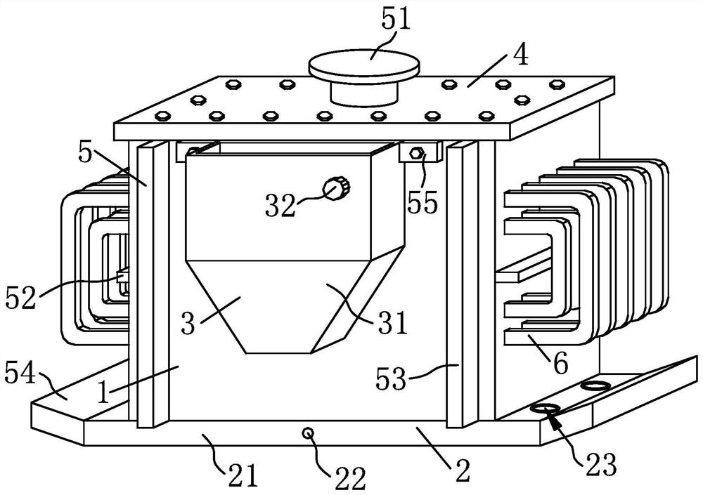
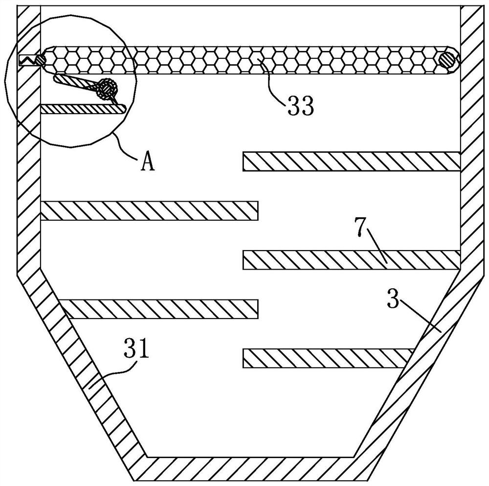
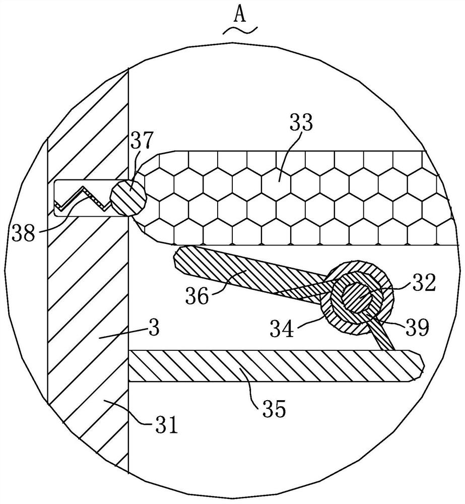
[0020] Depend on Figure 1-4 Given, a low-voltage welding transformer in the present invention includes a mounting shell 1, a transformer body 8 is installed inside the mounting shell 1, and a top plate 4 for shielding is detachably connected to the top of the mounting shell 1. The bottom end of the shell 1 is connected with a support structure 2 for supporting and limiting the transformer body 8, and the side wall of the installation shell 1 is connected with a heat dissipation structure 3 for heat dissipation of the transformer body 8 during operation. The installation shell 1 is connected with a cooling strip 6 that further improves the heat dissipation effect of the transformer body 8, the installation shell 1 is connected with an auxiliary structure 5 for the auxiliary work of the transformer body 8, and the heat dissipation structure 3 is ...


PUM


Abstract

A low-voltage welding transformer includes a mounting shell, a transformer body is installed inside the mounting shell, and a top plate for shielding is detachably connected to the top of the mounting shell. In rainy days, the rainwater drips into the inside of the box and contacts the filter plate, and when filtered by the filter plate, the rainwater enters the inside of the box for storage, so that the rainwater with high purity inside the box can affect the inside of the installation shell. When the transformer body is working, it absorbs heat and dissipates heat, which is beneficial to the work of the transformer body. The elastic force of the elastic strip pushes the limit ball against the filter plate, so that the filter plate can stably filter rainwater, isolate impurities at the top of the box, and prevent rainwater from being turbid and reducing absorption. Thermal efficiency, by turning the knob, the fixed plate is rotated to make the torsion spring generate elastic force, so that the ejector rod rotates clockwise to lift the filter plate and rotate clockwise, so that the filter plate rotates clockwise out of the inside of the box, and the limit ball slides away Filter plate, then the filter plate can be cleaned.

Description

technical field [0001] The invention relates to the technical field of transformers, in particular to a low-voltage welding transformer. Background technique [0002] Transformer is a device that uses the principle of electromagnetic induction to change AC voltage. The main components are primary coil, secondary coil and iron core (magnetic core). The main functions are: voltage conversion, current conversion, impedance conversion, isolation, voltage stabilization (magnetic Saturated transformer), etc., a transformer is a device that transforms AC voltage, alternating current, and impedance. When an AC current passes through the primary coil, an AC magnetic flux is generated in the iron core (or magnetic core), which induces a magnetic flux in the secondary coil. Voltage (or current), low-voltage welding transformer is a kind of transformer; the traditional outdoor installation transformer in the working process, the transformer generates a lot of heat, it is difficult to di...

Claims


Application Information

Patent Timeline
Patent Type & Authority Patents(China)
IPC IPC(8): H01F27/02H01F27/06H01F27/16H01F27/22
CPCH01F27/022H01F27/025H01F27/06H01F27/16H01F27/22
Inventor 夏玥冯松余良友陈梓雯
Owner 湖北金力特电气有限公司
Why Eureka
Eureka Blog
Learn More