
System and method for improving radio frequency in broadband wireless communication

A broadband wireless communication, radio frequency technology, applied in transmission systems, high-frequency amplifiers, transmission control/equalization, etc. Flexible methods and small structural constraints

Inactive Publication Date: 2020-07-10
博微太赫兹信息科技有限公司
View PDF7 Cites 0 Cited by
  • Summary
  • Abstract
  • Description
  • Claims
  • Application Information

AI Technical Summary

Problems solved by technology

The disadvantage of this method is that when the RF frequency is high, the analog mixers are cascaded more, the structure is complex, and the design is difficult
And affected by the device, the mixer clock is difficult to achieve more than 100 GHz, so it is difficult to design a radio frequency solution of more than 100 GHz in traditional electronics solutions, and existing devices cannot meet the requirements

Method used


Image

  • System and method for improving radio frequency in broadband wireless communication
  • System and method for improving radio frequency in broadband wireless communication
  • System and method for improving radio frequency in broadband wireless communication

Examples


Embodiment 1

[0026] This embodiment provides a technical solution: a system for increasing radio frequency frequency through broadband wireless communication, including a laser, an optoelectronic modulator, an optoelectronic converter and an antenna, the output end of the laser is connected to the input end of the optoelectronic modulator, The input end of the photoelectric converter is connected to the output end of the photoelectric modulator, the output end of the photoelectric converter is connected to the antenna, the laser generates a high-frequency optical signal and inputs it into the photoelectric modulator, and the photoelectric The modulator is loaded with a modulation signal, the high-frequency optical signal and the modulation signal are modulated in the photoelectric modulator and then input to the photoelectric converter, and the photoelectric converter converts the modulated optical signal into an electrical signal through The antenna transmits.

[0027] The system for incr...

Embodiment 2

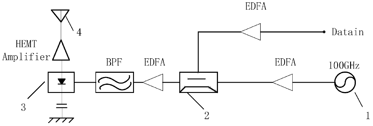
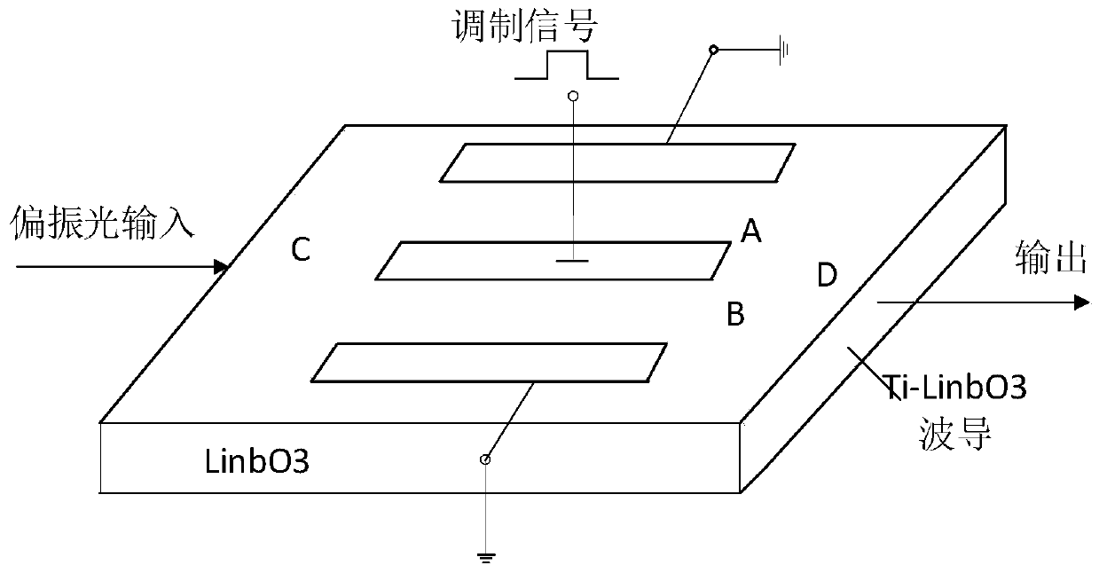
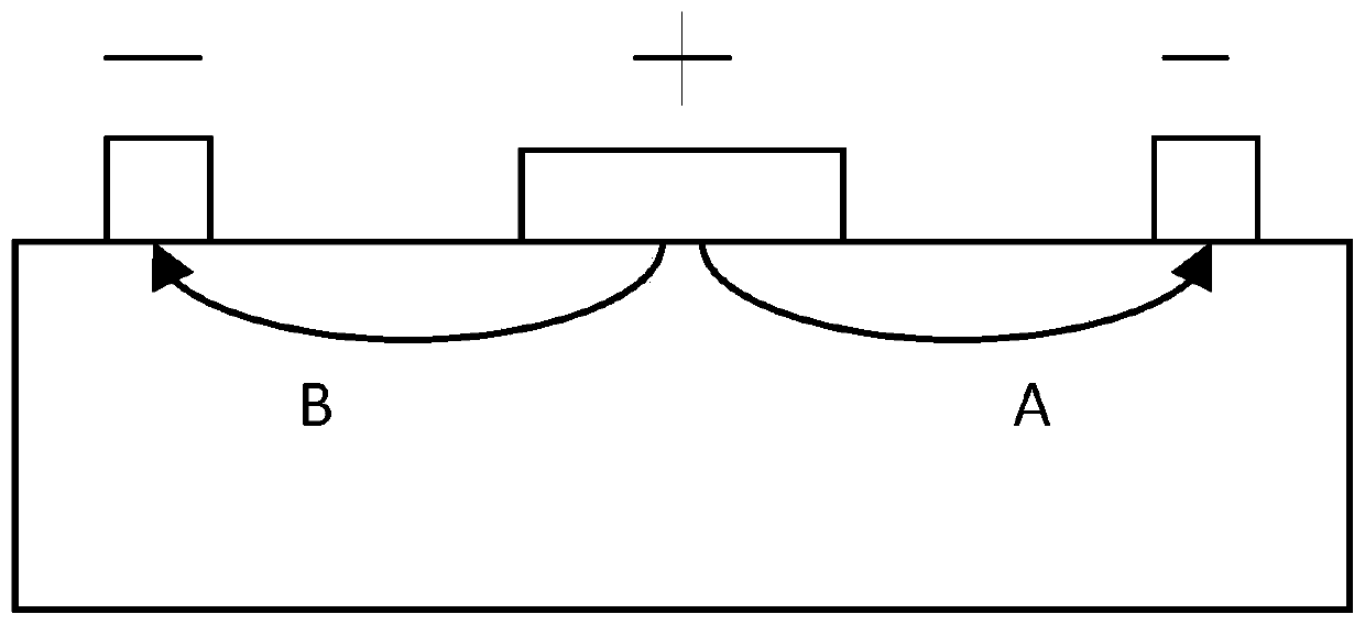
[0041] like figure 1 , 2 As shown in , 3, this embodiment proposes a system for increasing radio frequency frequency in broadband wireless communication. figure 1It is a structural schematic diagram of the system, which respectively includes a 100 GHz laser source 1 , a Mach-Zehnder amplitude modulator 2 and a Schottky barrier diode 3 along the electromagnetic wave propagation direction. The 100GHz laser source 1 generates light waves of corresponding wavelengths, and modulates them with the input digital signal (Datain) on the Mach-Zehnder amplitude modulator 2 after passing through the optical amplifier (EDFA). After modulation, the optical signal passes through the optical amplifier (EDFA), and then Input into the Schottky barrier diode 3 through a band-pass filter (BPF), use the Schottky barrier diode 3 to complete the photoelectric conversion process, and the converted high-frequency electrical signal passes through a high electron mobility transistor amplifier (HEMT Am...


PUM


Abstract

The invention discloses a system and a method for improving radio frequency through broadband wireless communication, and belongs to the technical field of wireless communication, and the system comprises a photoelectric modulator, a photoelectric converter, and a laser. According to the invention, the requirements of radio frequency on a high-speed ADC and a microwave circuit are greatly reduced,and a traditional PLL reference clock configurator is used as a clock source for simulating up-conversion. The clock frequency is influenced by devices, circuits and the like, the design is complex when the frequency is about 100GHz, the cost is relatively high, according to the invention, a broadband photoelectric modulation principle is utilized, under the condition that data transmission is not affected, signals are modulated through laser and then converted into electric signals through a photoelectric converter, due to the fact that the adjustable range of the wavelength of light waves is large, the radio frequency can be greatly improved, a PLL reference clock configurator and a high-speed DAC are omitted, and finally the purposes of improving performance and reducing device complexity are achieved.

Description

technical field [0001] The invention relates to the technical field of wireless communication, in particular to a system for increasing radio frequency in broadband wireless communication. Background technique [0002] Electricity and light are the most widely used transmission media in the field of information. Electricity, as a traditional and universal transmission medium, plays a pivotal role in various information systems, but it has some inevitable defects. Light, as a new transmission medium, has many advantages over electricity. Light is currently gradually replacing electricity in some specific areas, such as communication systems. However, in view of the fact that most of the current information systems are still based on electrical signals, and electrical signals are affected by devices in the radio frequency field, it is difficult to achieve a frequency of hundreds of GHz. Therefore, electricity can be used to modulate light and load signals on light. The elec...

Claims


Application Information

Patent Timeline
Patent Type & Authority Applications(China)
IPC IPC(8): H04B1/40H04B7/005H03F3/189
CPCH03F3/189H04B1/40H04B7/005
Inventor 汪忱张文翔
Owner 博微太赫兹信息科技有限公司
Learn More