
Waste heat comprehensive utilization system for rotary kiln

A rotary kiln and waste heat technology, which is applied in the direction of rotary drum furnace, waste heat treatment, lighting and heating equipment, etc., can solve the problems of the influence of the heat dissipation capacity of the rotary kiln and the adjustment of the amount of waste heat that cannot be recovered, so as to improve the heat dissipation efficiency and improve the Effects of heat dissipation performance, increased length, and heat-absorbing area

Active Publication Date: 2020-07-10
JIAXIAN ZHONGLIAN TIANGUANG CEMENT CO LTD
View PDF6 Cites 0 Cited by
  • Summary
  • Abstract
  • Description
  • Claims
  • Application Information

AI Technical Summary

Problems solved by technology

[0005] Although this waste heat recovery device on the outer wall of the cement rotary kiln can recover and utilize the waste heat of the rotary kiln, the relative position of the heat collector and the rotary kiln is fixed, and the waste heat recovery capacity of the heat collector to the rotary kiln in winter and summer is almost Similarly, the amount of waste heat recovery cannot be adjusted according to seasonal heat load changes, and the heat collector is covered on the outer wall of the rotary kiln, which usually has a great impact on the heat dissipation capacity of the rotary kiln in summer

Method used


Image

  • Waste heat comprehensive utilization system for rotary kiln
  • Waste heat comprehensive utilization system for rotary kiln
  • Waste heat comprehensive utilization system for rotary kiln

Examples


Embodiment Construction

[0033] The present invention will be described in further detail below in conjunction with the accompanying drawings.

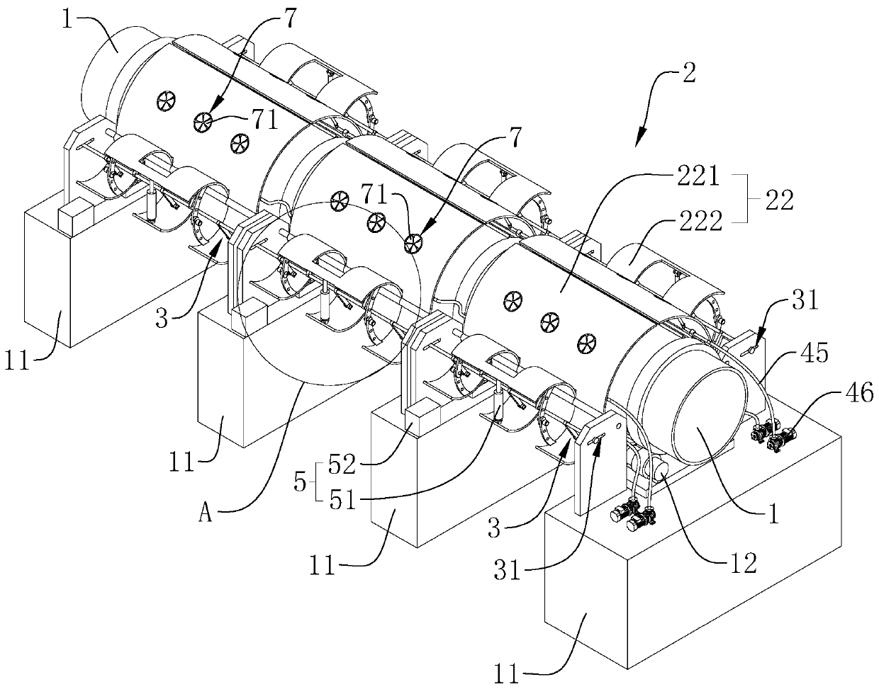
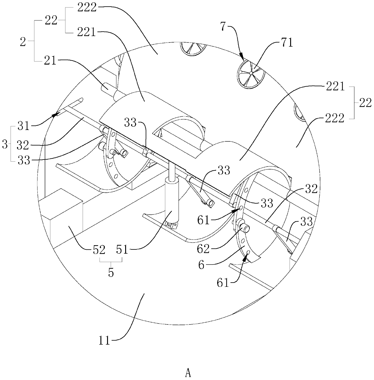
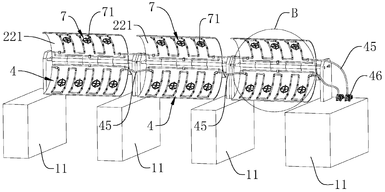
[0034] refer to figure 1 and figure 2 , is a rotary kiln waste heat comprehensive utilization system disclosed in the present invention, which includes a plurality of support piers 11 for supporting the rotary kiln shell 1, and also includes a heat collection mechanism 2 for absorbing the waste heat on the outer wall of the rotary kiln shell 1. The thermal mechanism 2 is connected to the load that needs to use hot water; each support pier 11 is provided with a supporting wheel mechanism 12 for supporting the rotary kiln shell 1, and the single-section rotary kiln shell 1 is supported on two adjacent support piers 11 on the two sets of tugboat mechanisms; the heat collecting mechanism 2 includes a support shaft 21 that is rotatably supported between two adjacent support piers 11, and each side of the rotary kiln shell 1 is respectively provided with a suppor...


PUM


Abstract

The invention relates to a waste heat comprehensive utilization system for a rotary kiln. The waste heat comprehensive utilization system for the rotary kiln comprises a plurality of supporting piers,and further comprises a heat collecting mechanism; the heat collecting mechanism is connected with a heat load; the heat collecting mechanism comprises supporting shafts each of which is rotatably supported between adjacent two supporting piers; the waste heat comprehensive utilization system for the rotary kiln further comprises two heat collecting plates hinged to the supporting shafts; each heat collecting plate comprises a heated arc plate arranged on a rotary kiln body and a control arc plate which is integrally arranged on the heated arc plate; a plurality of gaps are formed in the control arc plate; the two heat collecting plates on the same supporting shaft are arranged in a cross manner; the heat collecting mechanism is connected with a balance device; a heat absorbing pipe usedfor absorbing heat is arranged on the heated arc plate; and a power device is mounted between the two control arc plates on the same supporting shaft. According to the waste heat comprehensive utilization system for the rotary kiln has the effects of changing the heat collecting capacity of the heat absorbing pipe according to seasons and changing the radiating performance of the rotary kiln through the two heat collecting plates hinged to the supporting shaft by controlling the opening degree of the heat collecting plates by means of the power device.

Description

technical field [0001] The invention relates to the technical field of waste heat utilization of a rotary kiln, in particular to a comprehensive utilization system of waste heat of a rotary kiln. Background technique [0002] Rotary kiln is an important equipment in cement plant, used for calcining cement clinker. A rotary kiln is generally composed of a cylinder, a supporting device, a supporting device with retaining wheels, a transmission device, a movable kiln head, a kiln tail sealing device, a coal injection pipe device, a heating device and other components. During cement production, the cement raw material is sent into the kiln through the coal injection pipe device, the heating device heats the temperature in the kiln to above 1000 degrees, and the power transmission device drives the cylinder to rotate so that the raw material in the kiln is gradually calcined into clinker . During the calcination process of raw materials, the outer wall of the rotary kiln cylind...

Claims


Application Information

Patent Timeline
Patent Type & Authority Applications(China)
IPC IPC(8): F27D17/00F27B7/00F27B7/38
CPCF27B7/00F27B7/38F27D17/004Y02P10/25
Inventor 宋玉安符群安乔自绍陈高攀王佳佳
Owner JIAXIAN ZHONGLIAN TIANGUANG CEMENT CO LTD
Learn More