Diatom ooze coating and processing system and method thereof
A technology of diatom mud coating and processing system, applied in chemical instruments and methods, dissolution, mixer and other directions, can solve problems such as reducing operation efficiency
- Summary
- Abstract
- Description
- Claims
- Application Information
AI Technical Summary
Problems solved by technology
Method used
Image
Examples
specific Embodiment approach 1
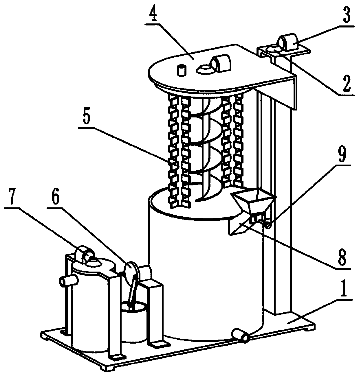
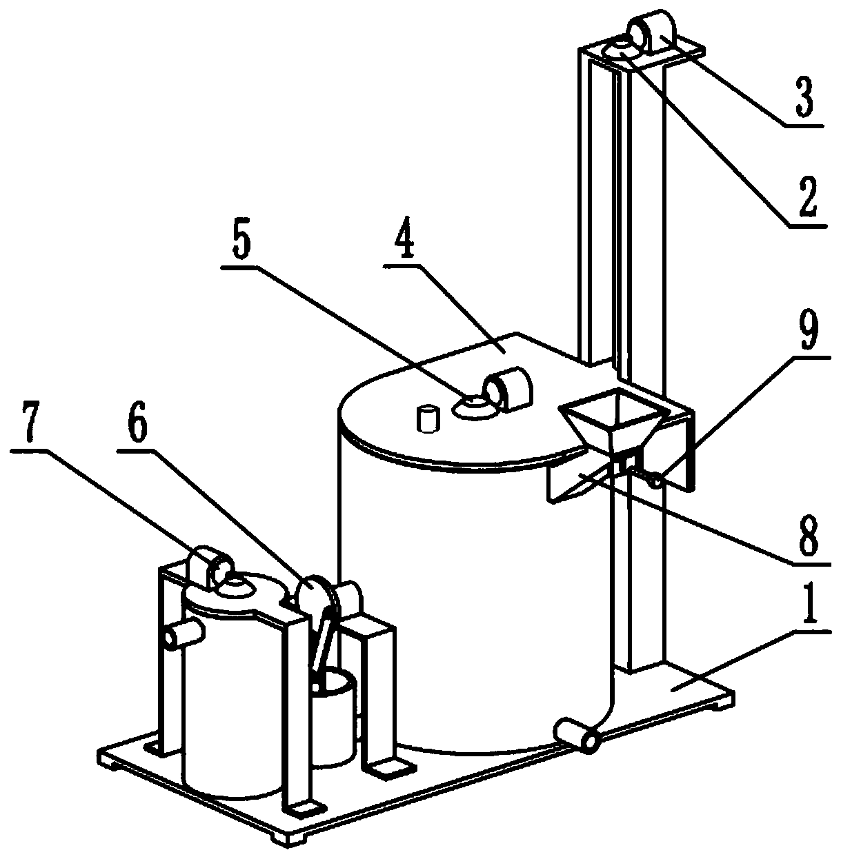
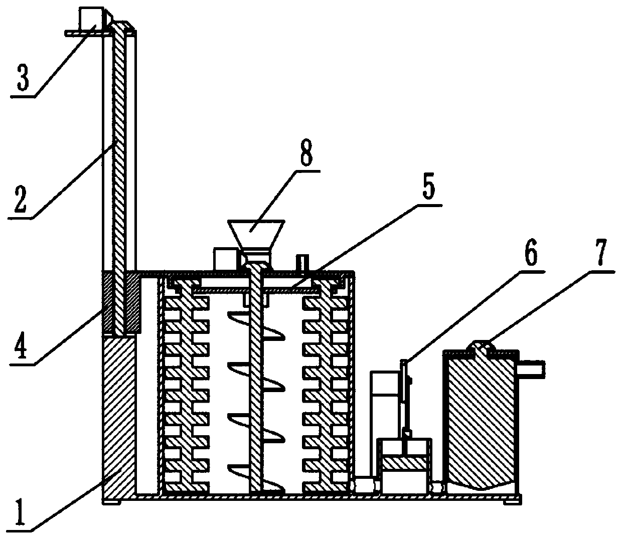
[0031] Such as Figure 1-10 As shown, a diatom mud coating processing system includes a support frame 1, a lifting threaded rod 2, a lifting motor 3, a lifting upper cover 4, a stirring mechanism 5, a piston mechanism 6, a grinding mechanism 7, a feeding pipe 8 and a feeding Blocking mechanism 9, the lifting threaded rod 2 is rotatably connected to the support frame 1, the lifting motor 3 is fixedly connected to the support frame 1, the lifting motor 3 and the upper end of the lifting threaded rod 2 are engaged for transmission, and the Lifting upper cover 4 is slidably connected on support frame 1, and lifting upper cover 4 is threadedly connected with lifting threaded rod 2, and described stirring mechanism 5 is connected on lifting upper cover 4, and described piston mechanism 6 and grinding mechanism 7 are both Fixedly connected on the support frame 1, the described feeding pipe 8 is fixedly connected on the supporting frame 1, and the described feeding blocking mechanism ...
specific Embodiment approach 2
[0034] Such as Figure 1-10As shown, the support frame 1 includes a support base 1-1, a bottom plate 1-2, a support column 1-3, an upper fixed plate 1-4, a stirring tank 1-5, a grinding tank 1-6, and a discharge pipe 1 -7, connecting pipe Ⅰ1-8, piston pipe 1-9, connecting pipe Ⅱ1-10 and sewage pipe 1-11, the four corners of the bottom plate 1-2 are provided with supporting base 1-1, and the supporting column 1-3 is fixedly connected On the bottom plate 1-2, the upper fixed plate 1-4 is fixedly connected to the upper end of the supporting column 1-3, and the stirring tank 1-5, the piston tube 1-9 and the grinding tank 1-6 are fixedly connected to the supporting base 1-1 in sequence Above, the connecting pipe II1-10 is connected between the mixing tank 1-5 and the piston pipe 1-9, the connecting pipe I1-8 is connected between the piston pipe 1-9 and the grinding tank 1-6, and the connecting pipe I1-8 and Connecting pipes II1-10 are equipped with one-way valves, the upper part o...
specific Embodiment approach 3
[0036] Such as Figure 1-10 As shown, the lifting upper cover 4 includes a cover plate 4-1, a threaded seat 4-2, a gear ring 4-3 and a water supply pipe 4-4, and the threaded seat 4-2 is fixedly connected to the back of the cover plate 4-1. end, the gear ring 4-3 is fixedly connected to the lower end surface of the cover plate 4-1, the water supply pipe 4-4 is fixedly connected to the upper end surface of the cover plate 4-1, and the threaded seat 4-2 is slidably connected to the support column 1-3 , the threaded seat 4-2 is threadedly connected with the lifting threaded rod 2;
[0037] Start the lifting motor 3 to drive the lifting threaded rod 2 to rotate, and through the threaded connection of the lifting threaded rod 2 and the threaded seat 4-2, the threaded seat 4-2 rises in the support column 1-3, thereby driving the cover plate 4-1 to rise.
PUM
 Abstract
Description
Claims
Application Information
 - R&D
- Intellectual Property
- Life Sciences
- Materials
- Tech Scout
- Unparalleled Data Quality
- Higher Quality Content
- 60% Fewer Hallucinations
Browse by: Latest US Patents, China's latest patents, Technical Efficacy Thesaurus, Application Domain, Technology Topic, Popular Technical Reports.
© 2025 PatSnap. All rights reserved.Legal|Privacy policy|Modern Slavery Act Transparency Statement|Sitemap|About US| Contact US: help@patsnap.com


