Sliding member and production method therefor

A sliding member and sliding surface technology, used in sliding contact bearings, rotating parts that resist centrifugal force, bearing components, etc., can solve the problem of cracks at the interface, reduced wear resistance, and insufficient wear resistance. question

Active Publication Date: 2020-07-07
DAIDO METAL CO LTD
View PDF16 Cites 0 Cited by
  • Summary
  • Abstract
  • Description
  • Claims
  • Application Information

AI Technical Summary

Problems solved by technology

[0004] However, in either of the conventional technologies, the strength of the bearing alloy layer of the sliding member is improved, but the wear resistance cannot be sufficiently ensured.
That is, in the case of citing Document 1, since the intermetallic compound contained in the bearing alloy layer becomes micronized, it is easy to fall off from the bearing alloy layer as the sliding surface wears out.
Therefore, there is a problem that the wear of the bearing alloy layer is increased and the wear resistance is lowered.
Similarly, in the case of citing Document 2, even if the strength of the parent phase of the bearing alloy layer is increased, the miniaturized intermetallic compounds tend to fall off from the bearing alloy layer, and the wear resistance decreases.
On the other hand, when the particle size of the intermetallic compound is increased to improve the wear resistance of the bearing alloy layer, cracks are likely to occur from the interface between the parent phase and the intermetallic compound

Method used


Image

  • Sliding member and production method therefor
  • Sliding member and production method therefor
  • Sliding member and production method therefor

Examples


Embodiment Construction

[0026] Hereinafter, one embodiment of the sliding member will be described based on the drawings.

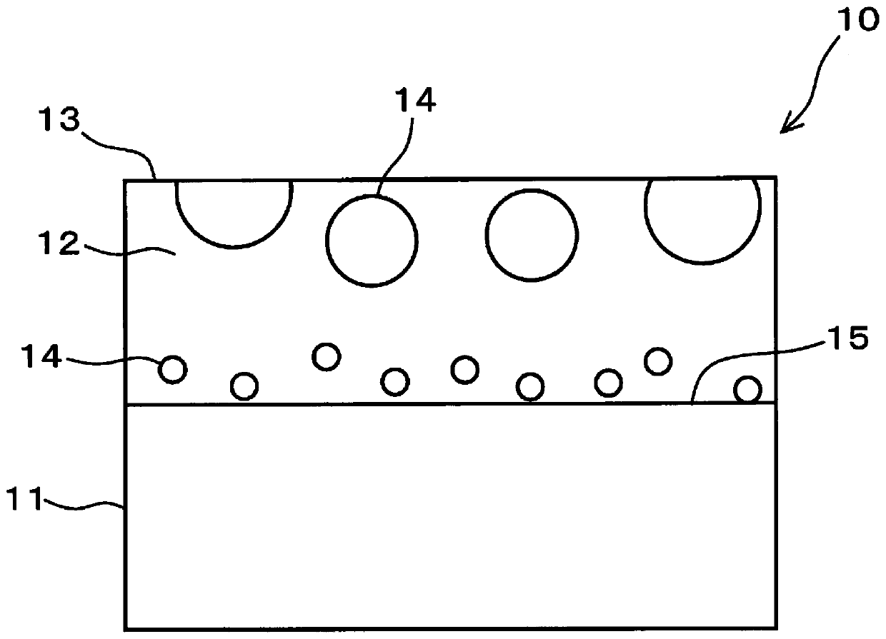
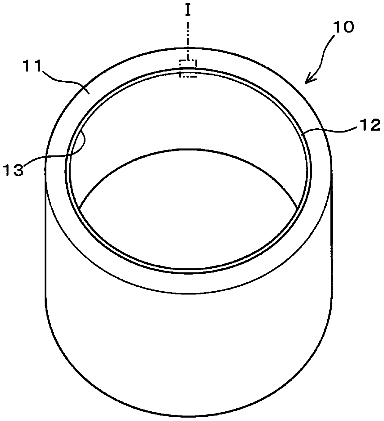
[0027] Such as figure 1 and figure 2 As shown, the sliding member 10 has an inner metal layer 11 and a bearing alloy layer 12 . The inner metal layer 11 is formed of, for example, Fe, steel typified by low carbon steel, or a copper alloy. The bearing alloy layer 12 is stacked on one end surface side of the back metal layer 11 . For example, if figure 2 As shown, in the case where the back metal layer 11 is formed in a cylindrical shape, the bearing alloy layer 12 is provided on the inner peripheral surface side of the back metal layer 11 . The bearing alloy layer 12 has a sliding surface 13 formed on the end surface opposite to the inner metal layer 11 . The sliding surface 13 slides with an unillustrated target member.

[0028] The bearing alloy layer 12 is formed of a Sn alloy mainly composed of Sn. Bearing alloy layer 12 in as figure 1 The structure shown contains i...


PUM


Abstract

A sliding member according to the present embodiment comprises a back metal layer, a bearing alloy layer, and an inter-metallic compound. The bearing alloy layer is layered upon the back metal layer and forms a sliding surface on the side opposite to the back metal layer. The inter-metallic compound is included in the structure of the bearing alloy layer and is harder than the average hardness ofthe entire bearing alloy layer, and in the bearing alloy layer, the average diameter of the particles of the inter-metallic compound on the side close to the sliding surface is larger than that on theside close to the back metal layer.

Description

technical field [0001] The present invention relates to a sliding member and a method of manufacturing the same. Background technique [0002] A sliding member used in a bearing device has a bearing alloy layer on a surface that slides with a counterpart member. The bearing alloy layer is used as a sliding member by being laminated with an inner metal layer such as steel. In order to reduce the burden on the environment, it is required to use a material that does not contain components such as Cd and Pb, for example, as the bearing alloy layer. Conventionally, a material that does not contain substances that impose a burden on the environment and satisfies the need for high strength has been proposed for a bearing alloy layer mainly composed of Sn or Cu (see Cited Documents 1 and 2). [0003] In the case of citing Document 1, intermetallic compounds precipitated in the bearing alloy layer are miniaturized by adding Co, Mn, Sc, Ge, etc. to Sn—Sb—Cu, which is a component of ...

Claims


Application Information

Patent Timeline
IPC IPC(8): F16C33/12C22C13/02F16C33/10F16C33/14F16C33/24
CPCF16C33/14C22C13/02F16C2204/34F16C17/00F16C33/125F16C2223/44F16C2240/08F16C2240/18F16C2240/26F16C2240/48F16C2240/60F16C2240/70F16C2300/14F16C2300/02F16C33/10F16C33/12F16C33/24
Inventor 原健良
Owner DAIDO METAL CO LTD
Why Eureka
Try Eureka