Gantry type numerical control machine tool capable of simultaneously performing tool changing and machining

A CNC machine tool and gantry type technology, which is applied in metal processing machinery parts, metal processing, metal processing equipment and other directions, and can solve the problems of low production efficiency, increased non-processing time of machine tools, and small duty cycle of machine tools.

Pending Publication Date: 2020-07-07
BEIJING JINGDIAO GRP CO LTD
View PDF0 Cites 3 Cited by
  • Summary
  • Abstract
  • Description
  • Claims
  • Application Information

AI Technical Summary

Problems solved by technology

[0002] When the existing gantry-type CNC machine tools perform single-station processing, each time a processing procedure is completed, the machine head needs to be moved to the tool change area for tool change. After the tool change, the machine head needs to be moved to the processing area for the next process. In the processing of the process, the tool change takes a long time, which affects the improvement of the processing efficiency, especially for the processing of 3C products. Due to the large number of processing steps and frequent tool changes, the non-processing time of the machine tool is greatly increased, and the duty cycle of the machine tool is small. Low production efficiency

Method used


Image

  • Gantry type numerical control machine tool capable of simultaneously performing tool changing and machining
  • Gantry type numerical control machine tool capable of simultaneously performing tool changing and machining
  • Gantry type numerical control machine tool capable of simultaneously performing tool changing and machining

Examples


Embodiment 1

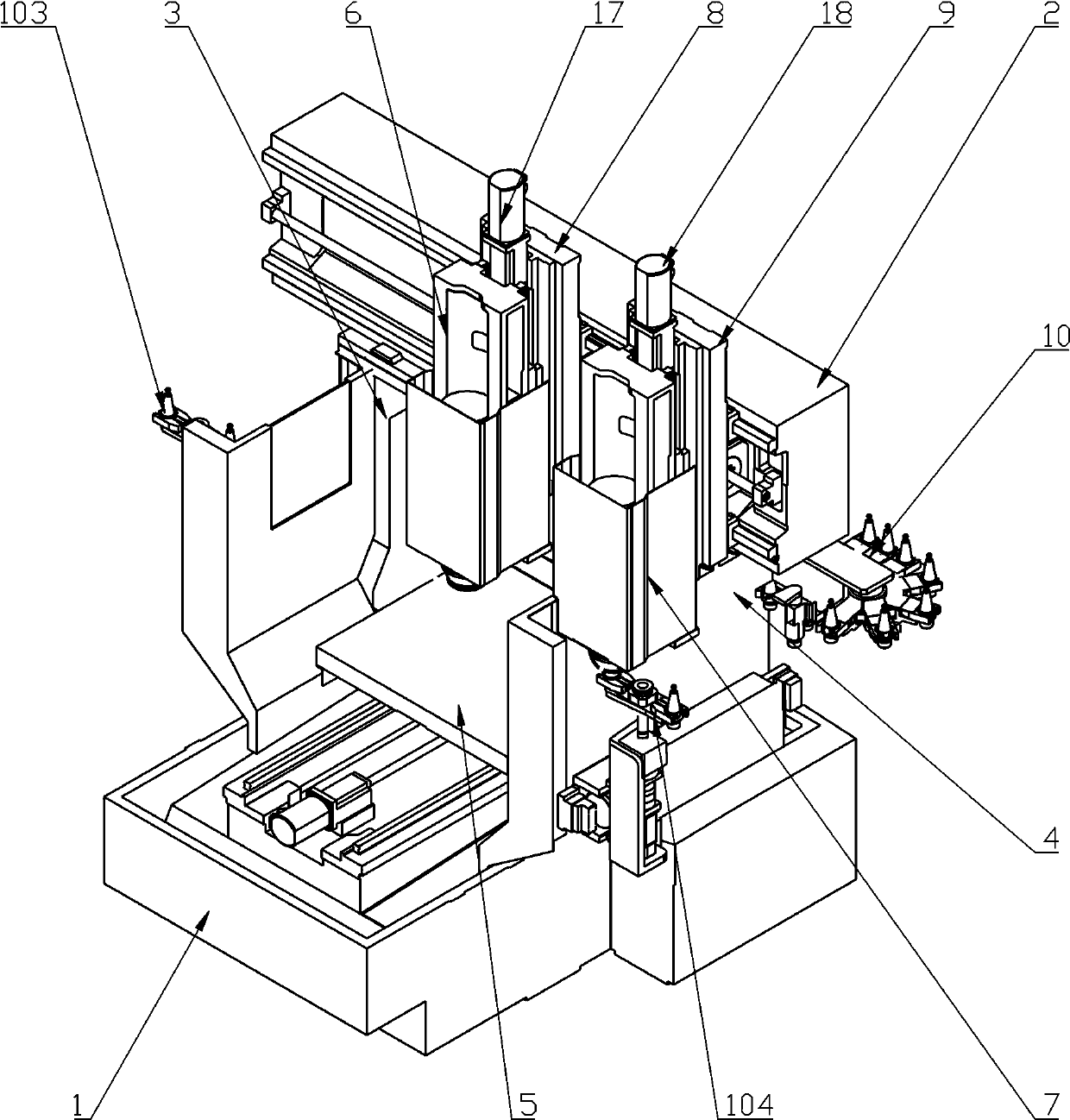
[0023] combine figure 1 , figure 2 with Figure 5 As shown, a gantry type CNC machine tool of the present invention which can carry out tool change and processing simultaneously is composed of a bed 1, a beam 2, a left column 3, a right column 4, a workbench assembly 5, a left head 6, and a right head 7. The first X sliding plate 8, the second X sliding plate 9, and the chain tool magazine 10 are composed.

[0024] The beam 2, the left column 3 and the right column 4 form a gantry structure and are fixed on the bed 1. The workbench assembly 5 is set under the beam 2 and is slidably installed on the bed 1. It can move along the Y direction under the action of the Y-axis drive assembly. reciprocating movement.

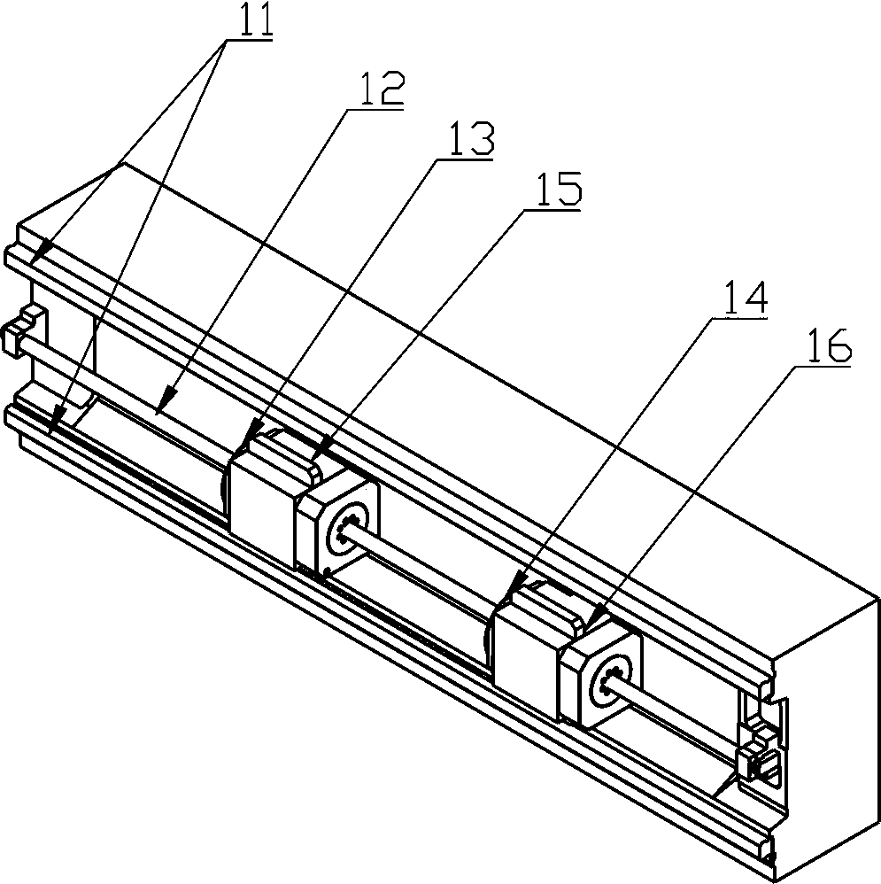
[0025] Two upper and lower guide rails 11 are arranged on the crossbeam 2 along the X direction, and a fixed lead screw 12 parallel thereto is arranged between the two guide rails 11 , and both ends of the fixed lead screw 12 are fixed on the crossbeam 2 . The fixed...

Embodiment 2

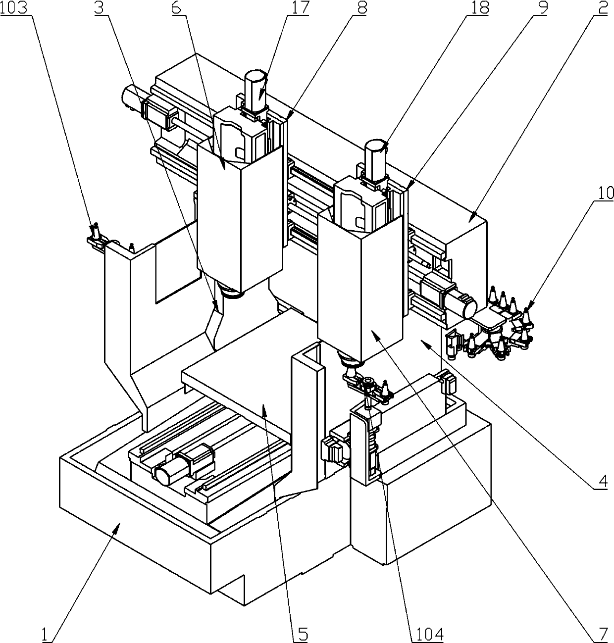
[0034] combine image 3 , Figure 4 with Figure 5 As shown, a gantry type CNC machine tool of the present invention which can carry out tool change and processing simultaneously is composed of a bed 1, a beam 2, a left column 3, a right column 4, a workbench assembly 5, a left head 6, and a right head 7. The first X sliding plate 8, the second X sliding plate 9, and the chain tool magazine 10 are composed.

[0035] The beam 2, the left column 3 and the right column 4 form a gantry structure and are fixed on the bed 1. The workbench assembly 5 is set under the beam 2 and is slidably installed on the bed 1. It can move along the Y direction under the action of the Y-axis drive assembly. reciprocating movement.

[0036] The crossbeam 2 is provided with two upper and lower guide rails 11 along the X direction, and a first rotating screw 19 and a second rotating screw 20 parallel to it are arranged between the two guide rails 11. The first rotating screw 19 and the second rotat...


PUM


Abstract

The invention relates to a gantry type numerical control machine tool capable of simultaneously performing tool changing and machining, and aims to realize multi-process non-intermittent continuous machining, the tool changing of the machine tool does not occupy the machining time, and the production efficiency is greatly improved. The gantry type numerical control machine tool is composed of a left machine head, a right machine head, a first X sliding plate, a second X sliding plate, a first X-axis driving assembly, a second X-axis driving assembly, a left Z-axis driving assembly and a rightZ-axis driving assembly, wherein the left machine head and the right machine head are installed on a cross beam through the first X sliding plate and the second X sliding plate respectively, can independently reciprocate in the X direction under the action of the first X-axis driving assembly and the second X-axis driving assembly respectively, and meanwhile, independently reciprocate in the Z-axis direction under the action of the left Z-axis driving assembly and the right Z-axis driving assembly respectively; and a numerical control system can control the right machine head to execute the tool changing action while controlling the left machine head to execute the machining action, and can also control the left machine head to execute the tool changing action while controlling the right machine head to execute the machining action.

Description

technical field [0001] The invention belongs to the field of numerical control machine tools, and in particular relates to a gantry type numerical control machine tool which can perform tool changing and processing simultaneously. Background technique [0002] When the existing gantry-type CNC machine tools perform single-station processing, each time a processing procedure is completed, the machine head needs to be moved to the tool change area for tool change. After the tool change, the machine head needs to be moved to the processing area for the next process. In the processing of the process, it takes a long time to change the tool, which affects the improvement of the processing efficiency, especially for the processing of 3C products. Due to the large number of processing steps and frequent tool changes, the non-processing time of the machine tool is greatly increased, and the duty cycle of the machine tool is small. Low production efficiency. Contents of the inventi...

Claims


Application Information

Patent Timeline
Patent Type & Authority Applications(China)
IPC IPC(8): B23Q37/00B23Q1/25B23Q3/155B23Q5/40
CPCB23Q1/25B23Q3/155B23Q5/402B23Q37/00
Inventor 蔚飞王岱张春玉
Owner BEIJING JINGDIAO GRP CO LTD
Why Eureka
Try Eureka