
Method and device for planning robot time optimal trajectory based on dynamic model

A dynamic model and time-optimized technology, applied in instruments, adaptive control, control/regulation systems, etc., can solve problems such as inability to discover robot performance, increase robot cost and energy consumption, and limit robot movement speed

Inactive Publication Date: 2019-09-06
SOUTH CHINA UNIV OF TECH +1
View PDF5 Cites 36 Cited by
  • Summary
  • Abstract
  • Description
  • Claims
  • Application Information

AI Technical Summary

Problems solved by technology

[0003] However, the movement speed of the robot is limited by its joint motors, mechanical structure and other conditions.
By increasing the power and size of the joint motors, the movement speed of the robot can be increased to a certain extent, but blindly increasing the power will increase the cost and energy consumption of the robot, and the inertia of the robot itself will decrease when the motor size increases. is increasing, and the increase in inertia is not conducive to the control of the robot
[0004] The motion of the robot is realized by trajectory planning. Conventional robot trajectory planning adopts trapezoidal acceleration trajectory planning, and only under the constraints of kinematic parameters, the kinematic parameters representing the robot are obtained by solving. This planning method is affected by joint coupling, and according to The constant acceleration set by experience or specific application scenarios cannot truly reflect the running state of the robot
In fact, the acceleration that the robot can provide changes with the change of its pose and load, which is closely related to the dynamic characteristics of the robot. Therefore, the conventional trajectory planning method cannot explore the potential performance of the robot.

Method used


Image

  • Method and device for planning robot time optimal trajectory based on dynamic model
  • Method and device for planning robot time optimal trajectory based on dynamic model
  • Method and device for planning robot time optimal trajectory based on dynamic model

Examples


Embodiment

[0084] Taking a six-degree-of-freedom industrial robot as the research object, the robot's time-optimized trajectory planning is carried out according to the following steps.

[0085] A dynamic model-based robot time optimal trajectory planning method, comprising steps:

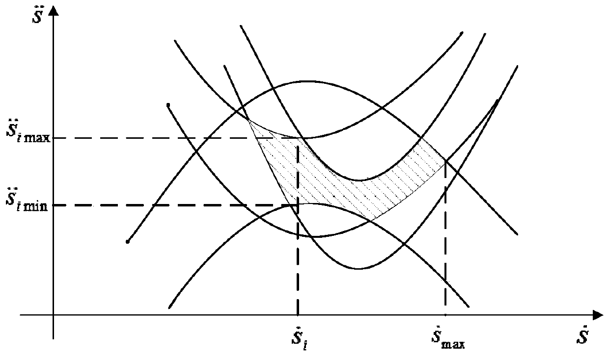
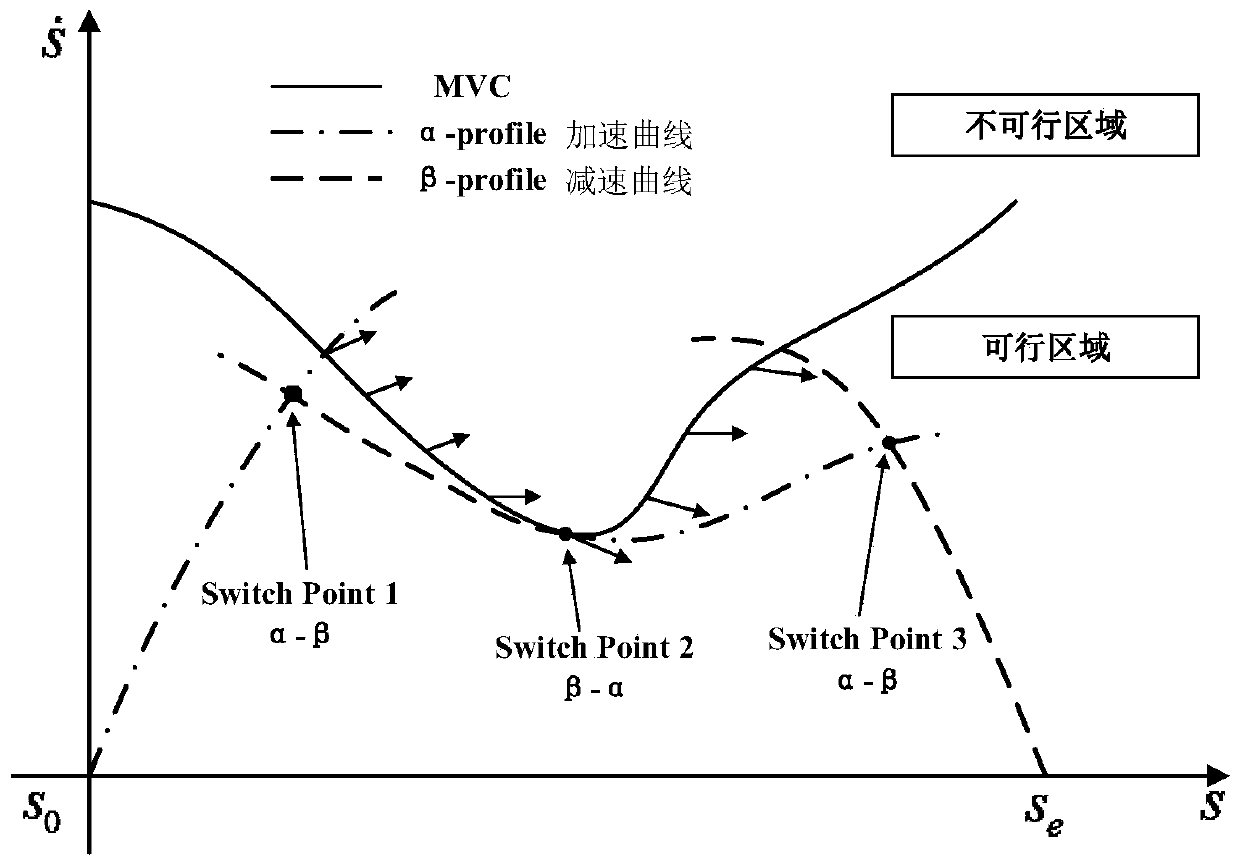
[0086] Establish the robot dynamic model and parameterize the robot's predetermined trajectory, and convert the joint torque constraints and geometric path constraints into the parameter space;

[0087] Construct an optimization problem with the shortest time as the goal and solve it by numerical integration method to obtain the optimal motion parameters of the robot;

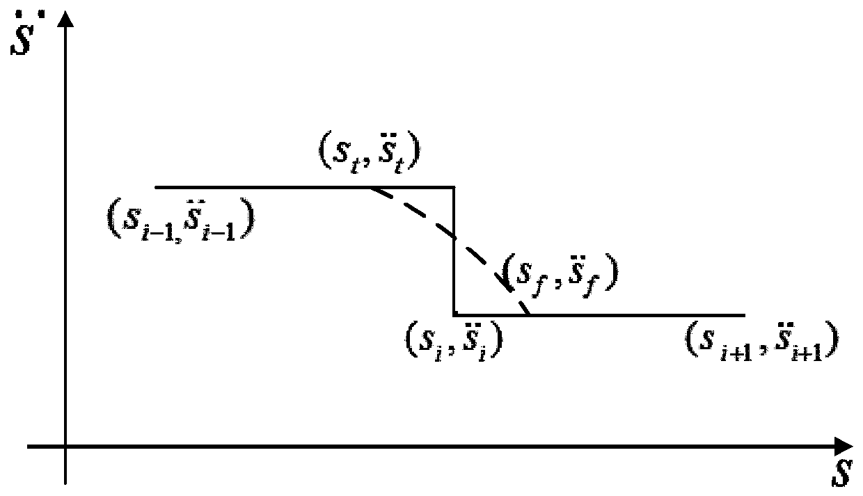
[0088] The optimized acceleration is smoothed with a cubic spline curve on the phase plane to avoid the vibration of the robot joints during the movement caused by sudden acceleration changes.

[0089] Further, the described establishment of robot dynamics model specifically includes steps:

[0090] For an n-degree-of-freedom industrial robo...


PUM


Abstract

The invention discloses a method and a device for planning a robot time optimal trajectory based on a dynamic model. The method for planning the robot time optimal trajectory comprises the following steps: converting joint motion constraint and geometric path constraint to a parameter space through a robot motion trajectory predetermined by dynamics modeling and parameterization; taking shortest time as an objective structural optimization problem, and solving through a numerical integration method to obtain an optimal motion parameter of the robot; and carrying out spline curve smoothing on acceleration for three times on a phase plane by considering the problem of joint vibration caused by sudden change of the acceleration. Compared with the conventional trapezoid acceleration trajectoryplanning method, the motion parameter of the robot can be optimized under the joint motion constraint and the geometric path constraint; the high-speed motion of the robot can be achieved; the performance of a joint motor is fully used; the motion speed of the robot can be further improved; pitch time for executing tasks is reduced, so that the operation efficiency of the robot is improved; and the method and the device have great significance to improvement of overall performance of the robot.

Description

technical field [0001] The invention relates to robot trajectory planning, in particular to a dynamic model-based robot time optimal trajectory planning method and equipment. Background technique [0002] With the development of robot technology, robots have been widely used in daily production and life, replacing humans to complete complex, dangerous, heavy and tedious repetitive tasks. In some application scenarios, such as palletizing, loading and unloading, etc., it is not only necessary for the robot to accurately complete the specified tasks, but also hope that the robot can complete the task as fast as possible, shorten the takt time, and improve its operating efficiency. [0003] However, the movement speed of the robot is limited by its joint motors, mechanical structure and other conditions. By increasing the power and size of the joint motors, the movement speed of the robot can be increased to a certain extent, but blindly increasing the power will increase the ...

Claims


Application Information

Patent Timeline
IPC IPC(8): G05B13/04
CPCG05B13/042
Inventor 张铁张美辉邹焱飚
Owner SOUTH CHINA UNIV OF TECH
Learn More