Synchronous waste heat recovery system for sintered flue gas circular online purification based on vertical sintering
A waste heat recovery system and a technology for sintering flue gas, applied in the fields of smelting equipment and energy conservation and environmental protection, can solve the problems of inefficient recovery of flue gas waste heat and residual energy, air leakage, serious problems, etc., so as to avoid sintering smoke and dust efflux, reduce particulate matter concentration, and reduce The effect of particulate matter concentration
- Summary
- Abstract
- Description
- Claims
- Application Information
AI Technical Summary
Problems solved by technology
Method used
Image
Examples
Embodiment 1
[0065] Example 1: Sintering flue gas circulation online purification and synchronous waste heat recovery system based on vertical sintering
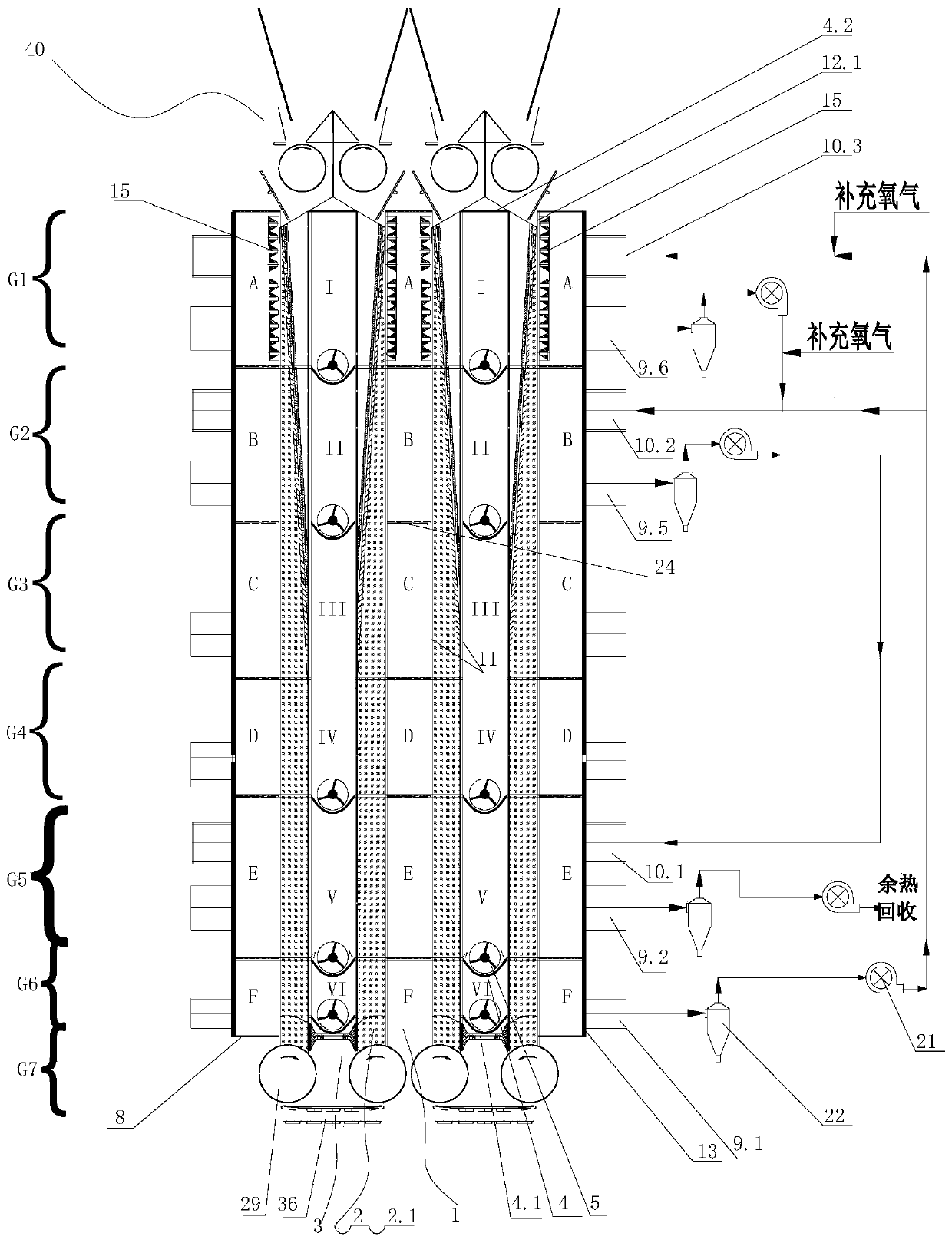
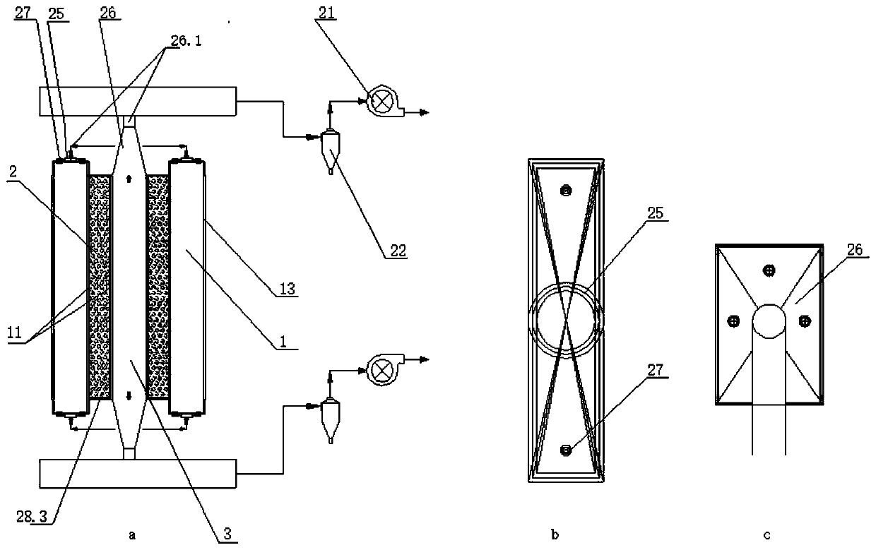
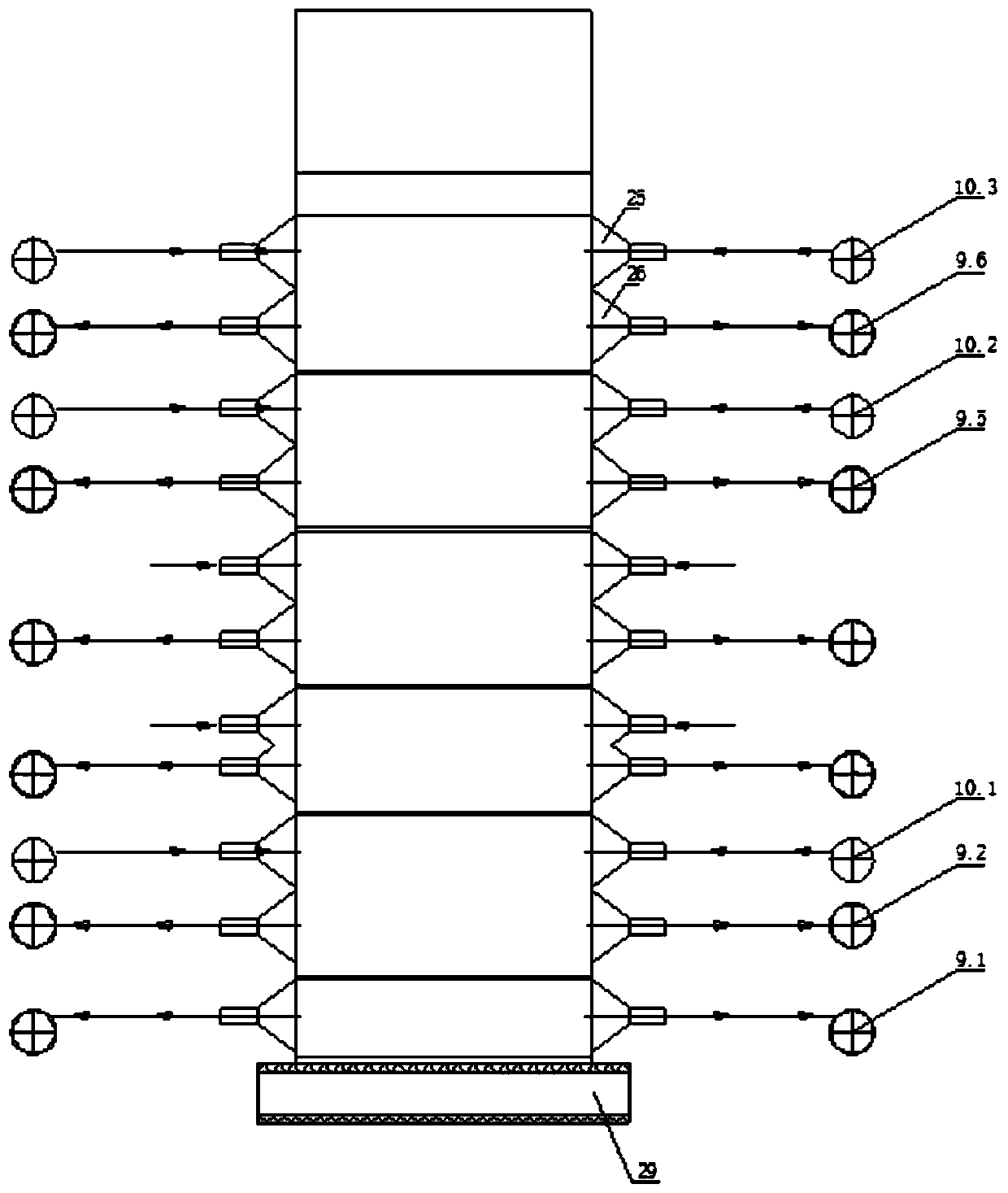
[0066] Such as figure 1 , figure 2 , image 3 As shown, the vertical sintering machine of the present invention includes 4 sintering chambers 2, 3 air inlet chambers 1, and 2 air outlet chambers 3. The sintering chamber 2 stands side by side between the air inlet chamber 1 and the air outlet chamber 3. The air inlet chamber 1 and the air outlet chamber 3 are separated by a grate bar 11 which is permeable to smoke;
[0067] The top of the gas outlet chamber 3 is closed and a discharge guide plate 6 is provided at the bottom. The gas outlet chamber 3 is composed of an ignition flue I, a low temperature flue II, a high SO 2 Flue III, low NO x Flue IV, high-temperature flue V, cooling flue VI are composed of six exhaust areas, ignition flue I, low-temperature flue II, low NO x The bottoms of the flue IV, the high-temperature flue V, an...
Embodiment 2
[0094] Example 2: Sintering flue gas circulation recovery waste heat and online desulfurization and denitrification system based on vertical sintering
[0095] Such as Figure 4 , the vertical sintering machine includes 16 sintering chambers 2, 9 inlet chambers 1, and 8 outlet chambers 3. The sintering chamber 2 stands side by side between the inlet chamber 1 and the outlet chamber 3. The air outlet chamber 3 is separated by a grate bar 11 that can permeate the smoke; similar to that of embodiment 1 figure 1 The structure shown, such as Figure 8 In this embodiment, the air inlet chamber 1, the air outlet chamber 3, and the sintering chamber 2 are divided into multiple identical areas from top to bottom:
[0096] The intake chamber 1 includes the following intake areas: ignition channel A, low temperature channel B, SO 2 Concentration increasing channel C, NO x Concentration reduction channel D, high temperature channel E, and cooling channel F; each air intake area in the...
PUM
 Abstract
Description
Claims
Application Information
 - R&D Engineer
- R&D Manager
- IP Professional
- Industry Leading Data Capabilities
- Powerful AI technology
- Patent DNA Extraction
Browse by: Latest US Patents, China's latest patents, Technical Efficacy Thesaurus, Application Domain, Technology Topic, Popular Technical Reports.
© 2024 PatSnap. All rights reserved.Legal|Privacy policy|Modern Slavery Act Transparency Statement|Sitemap|About US| Contact US: help@patsnap.com


