Mobile feeding mechanism used for injection molding machine and working method thereof

An injection molding machine, mobile technology, applied in the field of feeding mechanism, can solve the problems of easy shaking of materials, pollution, poor stability of feeding mechanism, etc., and achieve the effect of convenient connection, installation or disassembly, firm connection, and guaranteed convenience.

Active Publication Date: 2020-07-03
嘉兴市维尔塑业有限公司
View PDF7 Cites 0 Cited by
  • Summary
  • Abstract
  • Description
  • Claims
  • Application Information

AI Technical Summary

Problems solved by technology

[0004] The purpose of the present invention is to solve the problem that the existing feeding mechanism can only feed injection molding machines with the same height, shape and width, and the adaptability range of the work is small; and the feeding cylinder on the feeding mechanism moves to the injection molding machine The efficiency of feeding above the hopper is slow; the accuracy of the feeding mechanism for feeding is low; the feeding mechanism can only accommodate the same material for feeding, and when feeding different injection molding machines, it cannot be flexible and fast. type; and the loading capacity of the feeding mechanism for the material is low; the connection and installation or disassembly of the feeding barrel and the material box on the feeding mechanism is not convenient enough; during the feeding process of the feeding mechanism to the injection molding machine, the material is easy to shake off and splash into the injection molding Environmental pollution caused by the outside of the machine, the stability of the feeding mechanism is poor; and the safety of the feeding mechanism is poor when used, and a mobile feeding mechanism and its working method for injection molding machines are proposed

Method used


Image

  • Mobile feeding mechanism used for injection molding machine and working method thereof
  • Mobile feeding mechanism used for injection molding machine and working method thereof
  • Mobile feeding mechanism used for injection molding machine and working method thereof

Examples


Embodiment Construction

[0044] The technical solutions of the present invention will be clearly and completely described below in conjunction with the embodiments. Apparently, the described embodiments are only some of the embodiments of the present invention, not all of them. Based on the embodiments of the present invention, all other embodiments obtained by persons of ordinary skill in the art without creative efforts fall within the protection scope of the present invention.

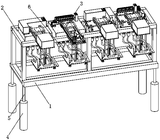
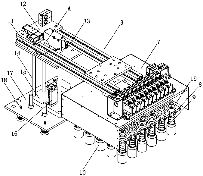
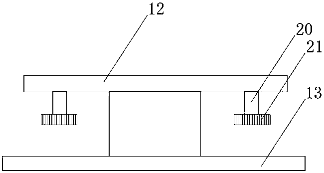
[0045] see Figure 1-11 As shown, a mobile feeding mechanism for an injection molding machine includes a horizontally arranged transmission carrier 1, a sleeve support frame 2, and a mounting platform 3. The sleeve support frame 2 is arranged above the transmission carrier 1, and the transmission carrier 1. The bottom is a rectangular structure. Hydraulic cylinders 4 are arranged vertically under the four corners of the bottom of the transmission carrier 1, and the upper part of the hydraulic cylinder 4 is vertically connec...


PUM


Abstract

The invention discloses a mobile feeding mechanism used for an injection molding machine and a working method thereof. The mobile feeding mechanism comprises a transmission carrying support, a sleevesupporting frame and hanging mounting tables which are arranged horizontally. The sleeve supporting frame is arranged above the transmission carrying support, and the bottom of the transmission carrying support is of a rectangular structure. Hydraulic oil cylinders are vertically arranged under the four corners of the bottom of the transmission carrying support correspondingly. The mobile feedingmechanism has the beneficial effects that third motors on the transmission carrying support drive the sleeve supporting frame to move left and right in an adjusting mode through third gears, and in amatched mode, first motors on the hanging mounting tables roll in rolling grooves through gears correspondingly, thus driving feeding drums to move front and back for adjustment; in addition, second motors drive rotary carrying plates and the feeding drums to rotate for adjusting positions through second gears, on the one hand, it is guaranteed that the feeding mechanism can perform feeding work on injection molding machines of different heights and widths and in different shapes, and on the other hand, it is guaranteed that the feeding drums move to the positions above a hopper more efficiently; and moreover, it is guaranteed that the mechanism performs feeding work on the injection molding machines more precisely, and the feeding quality of the feeding mechanism is improved.

Description

technical field [0001] The invention relates to a feeding mechanism, in particular to a mobile feeding mechanism for an injection molding machine and a working method thereof, and belongs to the technical field of feeding mechanism applications. Background technique [0002] After the injection molding machine has been used for a period of time, a feeding mechanism is required to add injection molding materials to the hopper of the injection molding machine to ensure the normal injection molding processing of the injection molding machine. [0003] The existing feeding mechanism for injection molding machines still has many deficiencies in use. The existing feeding mechanism can only perform feeding work on injection molding machines of the same height, shape, and width. Small, and the efficiency of the feeding cylinder 18 on the feeding mechanism moving to the top of the hopper of the injection molding machine is slow, and the accuracy of the feeding work of the feeding mec...

Claims


Application Information

Patent Timeline
IPC IPC(8): B29C45/18B29C45/17
CPCB29C45/1858B29C45/1866B29C45/17
Inventor 不公告发明人
Owner 嘉兴市维尔塑业有限公司
Why Eureka
Try Eureka