Boiler dust collection device
A dust collection device and boiler technology, which is applied in the direction of combination device, transportation and packaging, and dispersed particle filtration, etc., can solve the problems of poor dust removal effect, achieve better effect, improve utilization rate, and improve filtering effect
- Summary
- Abstract
- Description
- Claims
- Application Information
AI Technical Summary
Problems solved by technology
Method used
Image
Examples
Embodiment 1
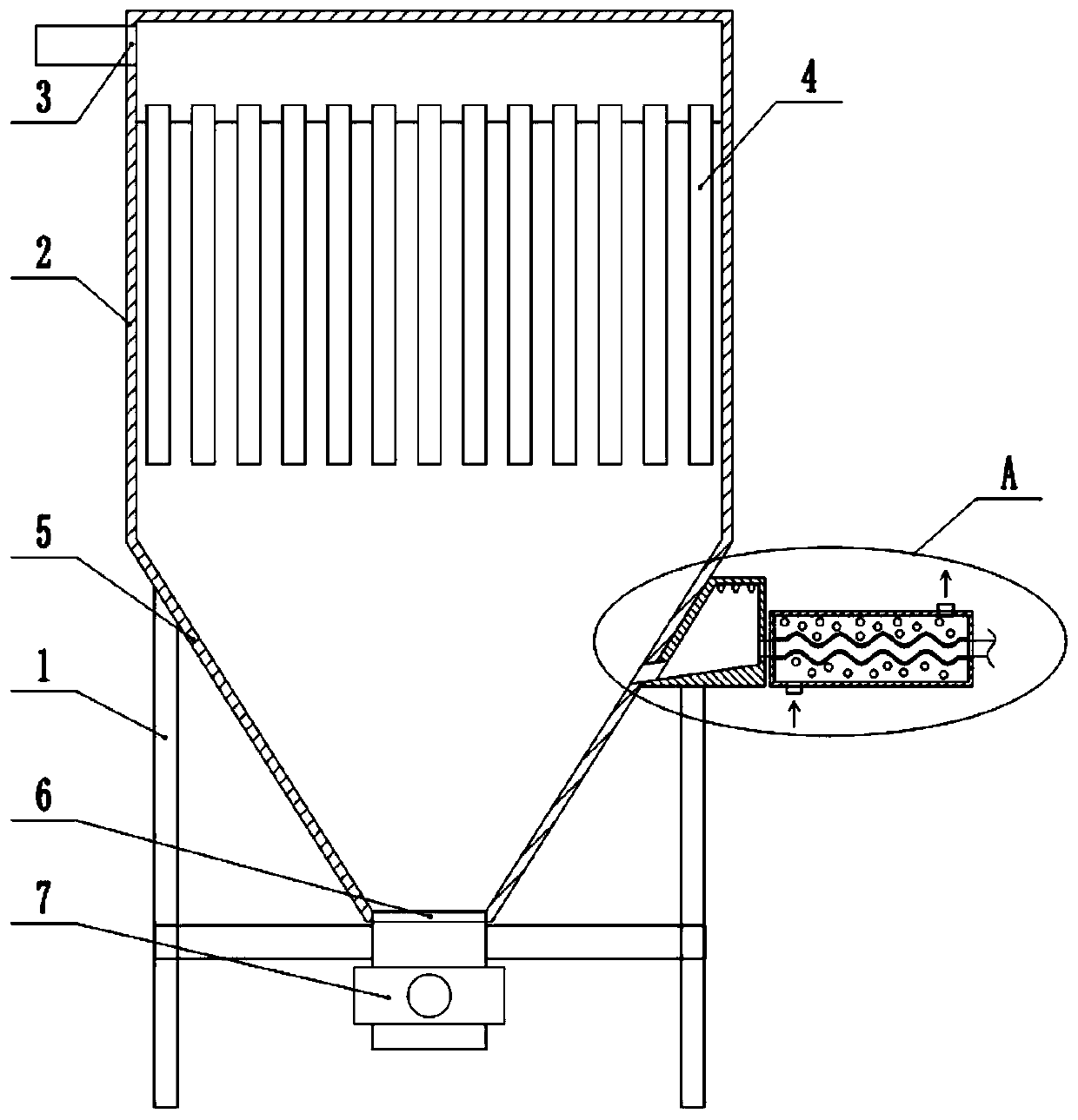
[0028] Embodiment one is basically as attached Figures 1 to 3 Shown:
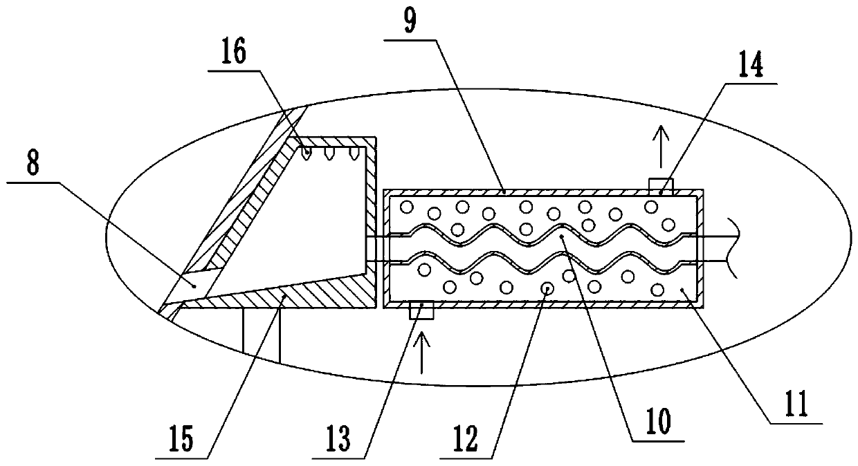
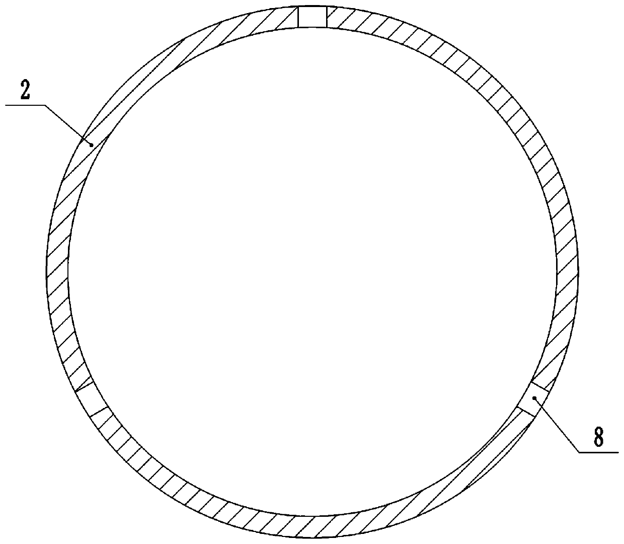
[0029] A dust collection device for a boiler, comprising a frame 1, a box 2 is fixedly connected to the frame 1 by bolts, an exhaust port 3 is opened on the box 2, a cloth bag 4 is fixed inside the box 2, and the bottom of the box 2 It is connected with an ash hopper 5, and the bottom of the ash hopper 5 is provided with a dust outlet 6, and a valve 7 is installed on the dust outlet 6, and an air inlet 8 inclined downward along the inner wall of the ash hopper 5 is opened on the side wall of the ash hopper 5, and the The number of air inlets 8 is an odd number greater than one, and the air inlets 8 are distributed in a circular array on the inner wall of the ash hopper 5 . In this embodiment, the number of air inlets 8 is three.
[0030] The frame 1 is provided with a cooling mechanism and a fire extinguishing mechanism. The cooling mechanism includes a cooling tube 9 communicated with the air inlet 8. Th...
Embodiment 2
[0032] Embodiment two is basically as attached Figure 4 Shown:
[0033] The difference between this embodiment and Embodiment 1 is that the cooling mechanism also includes a plurality of nozzles 17 arranged in the box body 2. The nozzles 17 are located below the cloth bag 4 and are distributed in a circular array on the side wall of the box body 2. The box body 2 is fixedly connected with a water tank 18, and a conduit is connected between the water tank 18 and the nozzle 17, and a one-way valve is installed on the conduit to conduct one-way to the tank 2, and a water pump is installed in the water tank 18, which can pump the water in the water tank 18 into In the conduit, water is sprayed from the shower nozzle 17. A water guide pipe 19 is connected between the water tank 18 and the water outlet 14, and a three-way valve 20 is installed on the water guide pipe 19. The box body 2 is fixed with a first filter net 21 and a second filter net 22 by bolts, the cloth bag 4 is loc...
Embodiment 3
[0036] Embodiment three is basically as attached Figure 5 Shown:
[0037] The difference between the present embodiment and the second embodiment is that a temperature sensor 23 is installed on the side wall of the ash hopper 5 close to the air inlet 8, and a controller (not shown) is fixedly connected to the frame 1 by bolts. The water pump, the temperature sensor 23 and the controller form an electrical connection. In this embodiment, the temperature sensor 23 and the controller are both existing in the prior art, and will not be repeated here.
[0038] During specific implementation, the temperature of the gas entering the ash hopper 5 is detected by the temperature sensor 23. When the temperature is too high, the controller controls the water pump to start, and the water in the water tank 18 is introduced into the shower nozzle 17 for spraying to cool down; When it is high, the water pump will not start. The range of this temperature is determined according to the actua...
PUM
 Abstract
Description
Claims
Application Information
 - Generate Ideas
- Intellectual Property
- Life Sciences
- Materials
- Tech Scout
- Unparalleled Data Quality
- Higher Quality Content
- 60% Fewer Hallucinations
Browse by: Latest US Patents, China's latest patents, Technical Efficacy Thesaurus, Application Domain, Technology Topic, Popular Technical Reports.
© 2025 PatSnap. All rights reserved.Legal|Privacy policy|Modern Slavery Act Transparency Statement|Sitemap|About US| Contact US: help@patsnap.com


