A weir type transition bag for thin strip continuous casting

A thin strip and continuous casting technology, which is applied in the field of iron and steel manufacturing, can solve the problems of small transition ladle capacity, uneven tapping temperature, cold steel blockage, etc., and achieve the goals of reducing slag inclusion defects, improving product quality, and increasing molten steel temperature Effect

Active Publication Date: 2022-02-25
SHAGANG GROUP +2
View PDF10 Cites 0 Cited by
  • Summary
  • Abstract
  • Description
  • Claims
  • Application Information

AI Technical Summary

Problems solved by technology

[0003] At present, in the thin strip continuous casting production process, it is found that the tapping temperature at each outlet hole is extremely uneven, the tapping temperature at the middle outlet hole is high, and the tapping temperature at the side outlet hole is low, with a temperature difference exceeding 20°C; The liquid outlet hole is often blocked by the cold steel due to the low temperature of the molten steel, and the probability of blockage is about 5%.
The above situation will lead to uneven temperature distribution of the molten steel in the molten pool along the width direction of the casting strip, which will affect the shape of the casting strip, and the convexity of the casting strip will be greater than 50 μm; As a result, cast strip products often have slag inclusion defects, which limits the improvement of product quality
[0004] At present, there are very few patents or applications for transition ladles for thin strip continuous casting, which involve how to reduce the tapping temperature difference at the distributed outlet holes of the transition ladle, reduce the blockage of the liquid outlet holes at the edge, and fully promote the process of melting steel. Patents or applications for floating inclusions are even rarer

Method used


Image

  • A weir type transition bag for thin strip continuous casting
  • A weir type transition bag for thin strip continuous casting

Examples


Embodiment Construction

[0028] In order to make the purpose, technical solutions and advantages of the embodiments of the present invention clearer, the technical solutions of the embodiments of the present invention will be clearly and completely described below. Apparently, the described embodiments are some, not all, embodiments of the present invention. Based on the described embodiments of the present invention, all other embodiments obtained by persons of ordinary skill in the art without creative efforts shall fall within the protection scope of the present invention.

[0029] Unless otherwise defined, the technical terms or scientific terms used in the present invention shall have the ordinary meanings understood by those having ordinary skill in the art to which the present invention belongs.

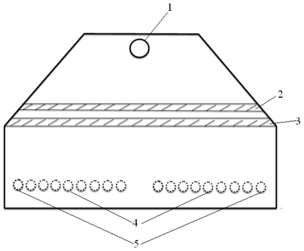
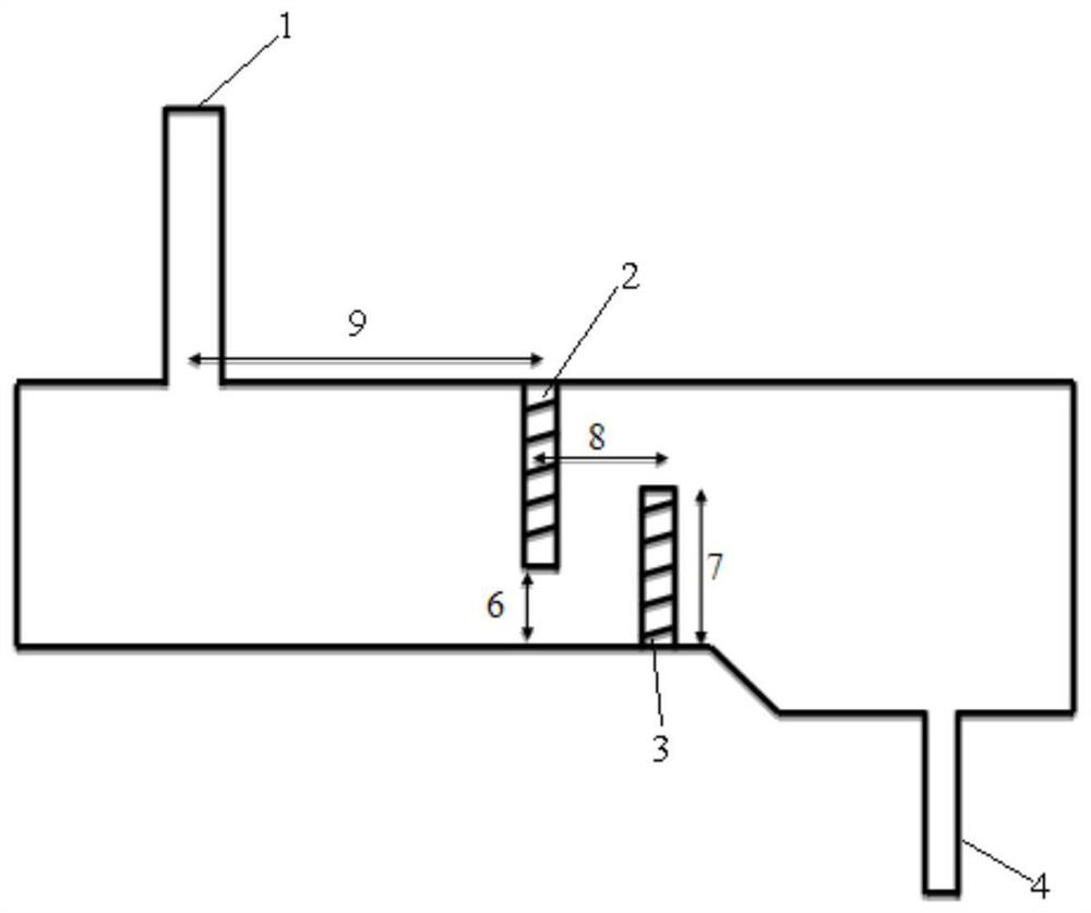
[0030] refer to figure 1 with figure 2 , which shows a weir-type transition bag for thin strip continuous casting according to an embodiment of the present invention.

[0031] Such as figure 1 ...


PUM


Abstract

The invention belongs to the field of iron and steel manufacturing, and relates to a weir type transition bag for thin strip continuous casting. In the present invention, a combination of a dam and a dam is arranged inside the transition bag. After the molten steel enters from the entrance of the transition bag, it passes through the bottom of the weir one by one. After the liquid level rises, it crosses the top of the dam, enters the distributed outlet holes of the transition bag, and flows out of the transition bag evenly. With reasonable weir-to-entrance distance, weir height, dam height, and weir-dam spacing parameters, this setting can effectively reduce the steel tapping temperature difference of each liquid outlet hole in the transition bag, increase the molten steel temperature at the edge liquid outlet hole, and reduce the The blockage of the liquid outlet holes at the edge can be improved, thereby improving the temperature uniformity of the molten steel in the subsequent molten pool, and optimizing the strip shape; at the same time, this dam weir setting can fully promote the floating of inclusions in the molten steel, reduce slag inclusions in the casting strip, and improve product quality.

Description

technical field [0001] The invention belongs to the field of iron and steel manufacturing, and in particular relates to a weir type transition bag for thin strip continuous casting. Background technique [0002] Thin strip continuous casting technology is a new type of thin strip steel production process. Compared with the traditional hot rolling process, it has the advantages of less equipment investment, simple production process, low energy consumption, and low product cost. Mature thin strip continuous casting technology adopts three-pack structure, namely ladle, tundish and transitional bag. The molten steel flows from the ladle into the tundish in sequence, then into the transition ladle, and finally flows out from the distributed outlet holes in the transition ladle, and enters the subsequent molten pool to form a casting belt. Among them, the transition bag is a unique design in the thin strip continuous casting technology. Its distributed outlet holes play the role...

Claims


Application Information

Patent Timeline
Patent Type & Authority Patents(China)
IPC IPC(8): B22D41/02B22D41/50B22D43/00
CPCB22D41/02B22D41/50B22D43/001
Inventor 郭海荣李化龙李建伟施一新周东升刘玉君
Owner SHAGANG GROUP
Why Eureka
Try Eureka