Anode photosynthetic solar fuel cell system
A fuel cell system and fuel cell technology, applied in the field of plant-microbial fuel cells, can solve problems such as inability to meet large-scale production applications, low electrical energy conversion rate, etc., and achieve the effects of high energy conversion efficiency and mild reaction conditions
- Summary
- Abstract
- Description
- Claims
- Application Information
AI Technical Summary
Problems solved by technology
Method used
Image

Examples
Embodiment 1
[0032] Embodiment 1 Construction of anode photosynthetic solar fuel cell system
[0033] The root layer soil of Changzhou City Wetland Park in Jiangsu Province was collected, the pH value was 7.58, the soil moisture content was 37.52%, the salt content was 0.58%, the organic matter content was 19.37g / kg, the total nitrogen content was 2.75g / kg, and the available potassium content was 95.76mg / kg. Phosphorus content 43.56mg / kg, reserved for future use
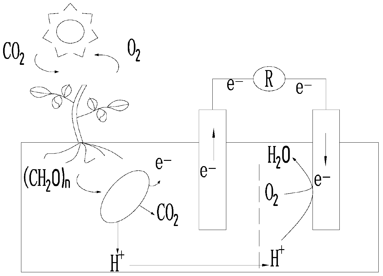
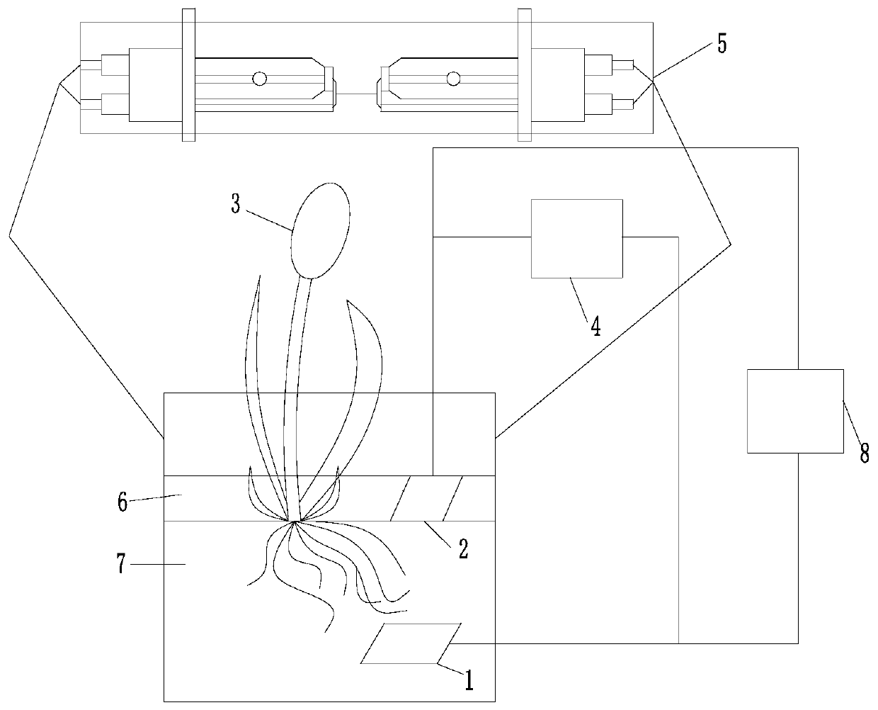
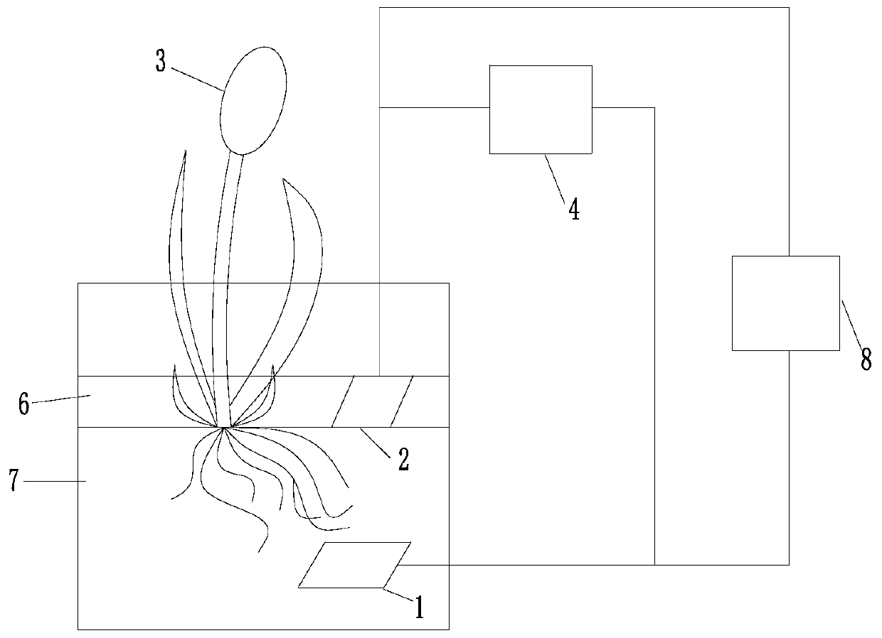
[0034] like figure 2 As shown, the anode photosynthetic solar fuel cell system described in this embodiment includes an anode photosynthetic solar fuel cell (APSFCs), a resistor (4) and a xenon lamp group (5), and the anode photosynthetic solar fuel cell is a single-chamber structure, including Soil (7), water body (6), green aquatic plants (3) and two electrodes, the roots of the green aquatic plants (3) are placed inside the soil (7) through the water body (6), and one of the electrodes is tiled The inside of the soil is use...
Embodiment 2
[0035] Embodiment 2 Preparation method of anode photosynthetic solar fuel cell system
[0036] The specific preparation method of the anode photosynthetic solar fuel cell system described in this embodiment is as follows: take the plant root layer soil (7) in Changzhou Wetland Park, Jiangsu, after air-drying, grind and sieve to obtain the soil (7) matrix for planting plants; then select Cattail plants are cultivated in opaque, non-conductive black plastic pots filled with soil (7); graphite felt is selected as the cathode (2); nickel foam is used as a 3D support, and biomass porous carbon is used for its Foam nickel carries out surface modification as anode (1), and the specific surface area of described biomass porous carbon is 3096m 2 / g, the specific capacitance is 268.49F / g; the cattail plant is planted in the growth box, and the cathode and anode of the system are placed in a symmetrical structure according to the length of the root system, wherein the size of the anode...
Embodiment 3
[0037] Example 3 Analysis of the influence of green plants and light conditions on the power generation capacity of fuel cells
[0038] The specific experimental scheme of this embodiment is as follows:
[0039] like Figure 5 to Figure 7 Build 3 groups of anode photosynthetic solar fuel cell systems (A1, A2, A3) as shown, and set Figure 4No plant control group (A0). Among them, A0 and A1 were set under normal sunlight conditions, and a xenon lamp was used to simulate sunlight, so that A2 was under continuous light conditions, and A3 plants were shaded with a shading bucket (9). The specific experimental groupings are shown in Table 1.
[0040] Table 1
[0041] Numbering A 0
A 1
A 2
A 3
plant none have have have light conditions normal sunshine normal sunshine continuous light shading
[0042] Add deionized water to each group of A1, A2, and A3 until the saturated water holding capacity of APSFCs is 800g / kg, place th...
PUM
| Property | Measurement | Unit |
|---|---|---|
| specific surface area | aaaaa | aaaaa |
| specific surface area | aaaaa | aaaaa |
Abstract
Description
Claims
Application Information
 - Generate Ideas
- Intellectual Property
- Life Sciences
- Materials
- Tech Scout
- Unparalleled Data Quality
- Higher Quality Content
- 60% Fewer Hallucinations
Browse by: Latest US Patents, China's latest patents, Technical Efficacy Thesaurus, Application Domain, Technology Topic, Popular Technical Reports.
© 2025 PatSnap. All rights reserved.Legal|Privacy policy|Modern Slavery Act Transparency Statement|Sitemap|About US| Contact US: help@patsnap.com