A Hall current sensor with buffer function

A Hall current and sensor technology, applied in the direction of only measuring current, measuring current/voltage, instruments, etc., can solve the problems of reducing sensor practicability and sensor damage, so as to improve practicability, reduce working temperature, and reduce the risk of damage The effect of chance

Active Publication Date: 2022-04-01
南京新捷中旭微电子有限公司
View PDF7 Cites 0 Cited by
  • Summary
  • Abstract
  • Description
  • Claims
  • Application Information

AI Technical Summary

Problems solved by technology

[0003] When the Hall current sensor of the prior art is in use, if the operating temperature of the sensor is too high, the sensor will be damaged. Not only that, after the Hall current sensor of the prior art is installed on the device, if the device vibrates too much, it will Can cause damage to the sensor, reducing the usefulness of the sensor

Method used


Image

  • A Hall current sensor with buffer function
  • A Hall current sensor with buffer function
  • A Hall current sensor with buffer function

Examples


Embodiment Construction

[0024] The present invention is described in further detail now in conjunction with accompanying drawing. These drawings are all simplified schematic diagrams, which only illustrate the basic structure of the present invention in a schematic manner, so they only show the configurations related to the present invention.

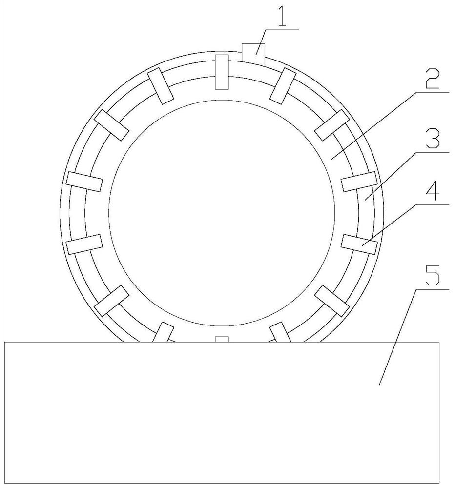
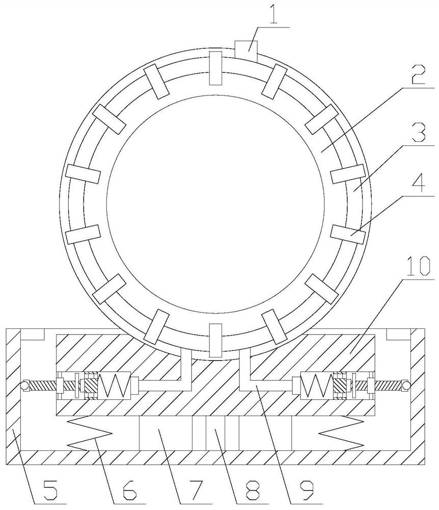
[0025] Such as figure 1 As shown, a Hall current sensor with a buffer function includes a main body 2 and a base 10, the main body 2 is fixedly connected to one end of the base 10, the base 10 is cylindrical in shape, and also includes a buffer mechanism and a heat dissipation mechanism , the buffer mechanism is arranged on the base 10, and the heat dissipation mechanism is arranged on the main body 2;

[0026] The vibration reduction function of the sensor is realized through the buffer mechanism, which reduces the probability of sensor damage. Not only that, the heat dissipation efficiency of the sensor is accelerated through the heat dissipation mechanism,...


PUM


Abstract

The invention relates to a Hall current sensor with a buffer function, which includes a main body and a base, and also includes a buffer mechanism and a heat dissipation mechanism. The buffer mechanism includes a mounting seat, at least two air bags, at least two first springs, at least two The damping assembly, the heat dissipation mechanism includes a heat pipe, an exhaust pipe and at least two air blowing assemblies, the damping assembly includes a second spring, a cylindrical recess, a piston block, a fixed bearing, a screw rod, a fan blade, Ball screw bearings and support rods, the air blowing assembly includes an air intake pipe, a first one-way valve, two through holes and two second one-way valves, in the Hall current sensor with buffer function, through the buffer mechanism The vibration reduction function of the sensor is realized, the probability of sensor damage is reduced, the heat dissipation efficiency of the sensor is accelerated through the heat dissipation mechanism, the working temperature of the sensor is reduced, and the probability of sensor damage is further reduced.

Description

technical field [0001] The invention relates to the field of Hall sensors, in particular to a Hall current sensor with a buffer function. Background technique [0002] The Hall current sensor is based on the magnetic balance Hall principle. According to the Hall effect principle, the current Ic is passed through the control current terminal of the Hall element, and a magnetic field with a magnetic induction intensity of B is applied in the normal direction of the Hall element plane. Then in the direction perpendicular to the current and the magnetic field (that is, between the Hall output terminals), a potential VH will be generated, which is called the Hall potential, and its magnitude is proportional to the control current I. and the product of magnetic induction B. That is, in the formula: K is the Hall coefficient, which is determined by the material of the Hall element; I. is the control current; B is the magnetic induction; VH is the Hall potential. [0003] When th...

Claims


Application Information

Patent Timeline
Patent Type & Authority Patents(China)
IPC IPC(8): G01R1/02G01R1/04G01R19/00
CPCG01R1/02G01R1/04G01R19/0092
Inventor 孙克翔谢凯王舒辞潘晓芳朱波谢璐琪
Owner 南京新捷中旭微电子有限公司
Why Eureka
Try Eureka