A control method of a hydraulic speed regulating system with manual automatic switching
A speed regulation system and control method technology, applied in the field of hydraulic system, can solve the problems of unreliable operation of hydraulic speed regulation system, trouble finding and troubleshooting, etc., and achieve the effects of neat appearance, reduction of leakage points, and easy installation.
- Summary
- Abstract
- Description
- Claims
- Application Information
AI Technical Summary
Problems solved by technology
Method used
Image
Examples
Embodiment 1
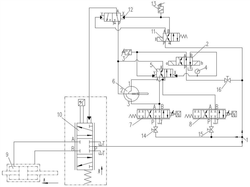
[0050] As the basic embodiment of the present invention, the present invention includes a control method of a hydraulic speed regulating system with manual automatic switching, including a main control hydraulic system, a pressure oil source 1, a two-position four-way switching solenoid valve 2, and a switch for monitoring the switching state. Pressure relay 1 3, pressure gauge 4, automatic switching hydraulic control reversing valve 5, manual switching valve 6, hydraulic signal output proportional valve 1 7 and hydraulic signal output proportional valve 2 8. The manual switching valve 6 is provided with oil port one, oil port two and oil port three.
[0051] Switching solenoid valve 2 adopts the structure of double electromagnets with position locking, which can avoid long-term charged operation of electromagnets. The P port of the switching solenoid valve 2 is connected to the pressure oil source 1, the T port is connected to the oil return, the output port A is connected to...
Embodiment 2
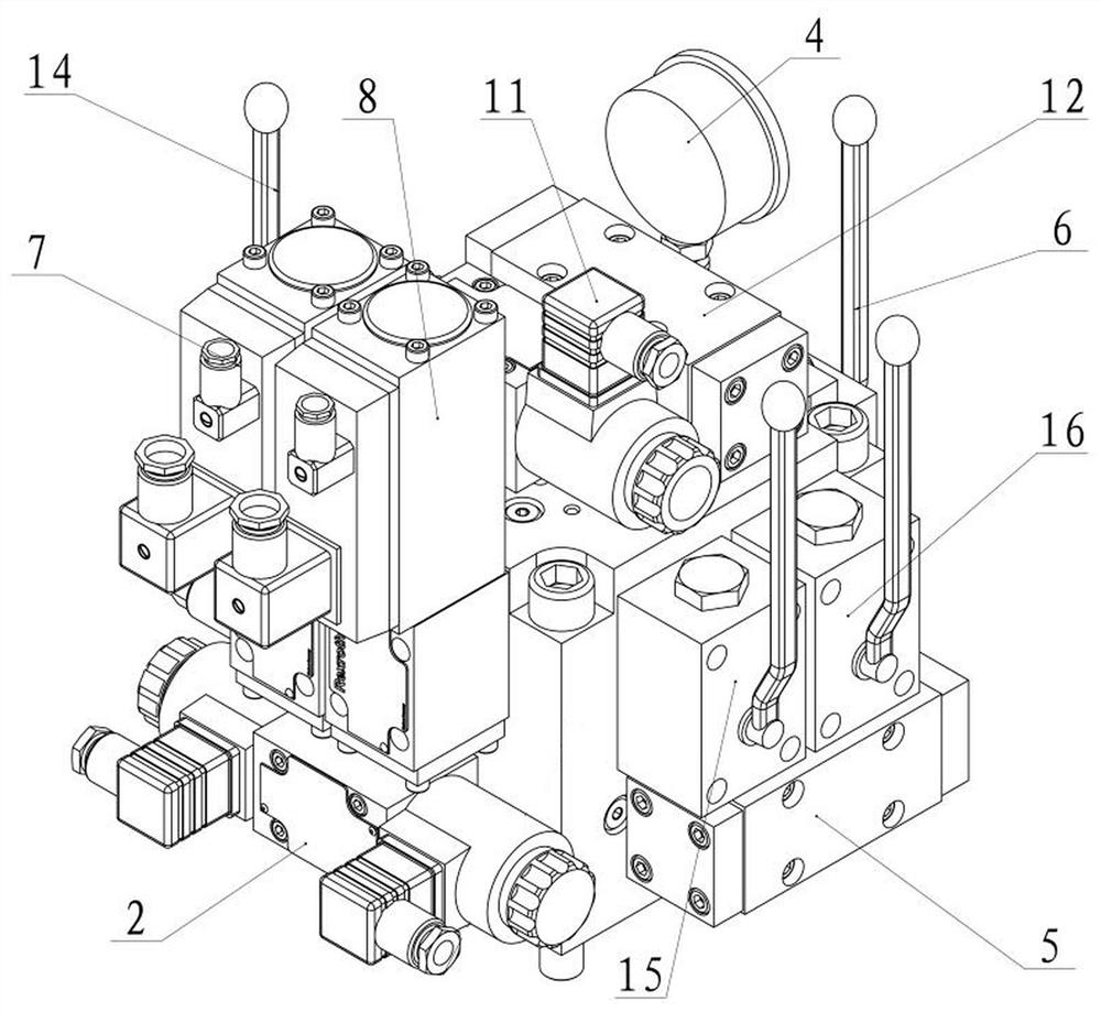
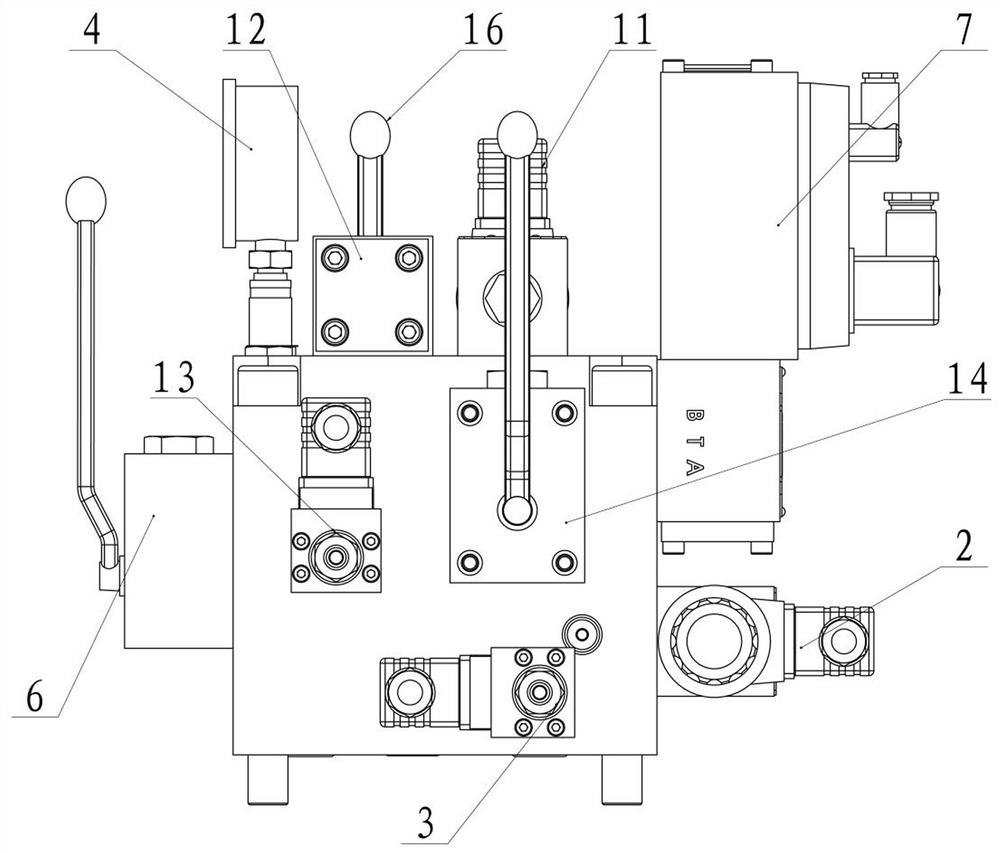
[0054] As a preferred embodiment of the present invention, with reference to the attached figure 1 , the present invention includes a control method of a hydraulic speed regulating system with manual automatic switching, including a pressure oil source 1, a two-position four-way switching solenoid valve 2, a pressure relay-3 for monitoring the switching state, a pressure gauge 4, an automatic switching Hydraulic control reversing valve 5, manual switching valve 6, hydraulic signal output proportional valve 1 7, hydraulic signal output proportional valve 2 8, guide vane servomotor 9, main pressure distribution valve 10, emergency stop solenoid valve 11, emergency stop hydraulic control Reversing valve 12, pressure relay 2 for monitoring shutdown 13, inspection ball valve 1 for inspection of hydraulic signal output proportional valve 1 14, inspection ball valve 2 for inspection of hydraulic signal output proportional valve 2 15, inspection switching solenoid valve 2 The maintena...
Embodiment 3
[0064] As another preferred embodiment of the present invention, the present invention includes a control method of a hydraulic speed regulation system with manual automatic switching, including a governor controller, a pressure oil source 1, a switching solenoid valve 2, an automatic switching hydraulic control Directional valve 5, manual switching valve 6, hydraulic signal output proportional valve 1 7, hydraulic signal output proportional valve 2 8, guide vane servomotor 9, main pressure distribution valve 10, emergency stop solenoid valve 11 and emergency stop hydraulic control reversing valve 12.
[0065] The main pressure distribution valve 10 is a three-position five-way slide valve structure, including an upper control chamber, a main valve spool and a lower control chamber. A spring is arranged in the lower control chamber, and the main pressure distribution valve 10 The switch chambers of ports A and B are respectively connected to the switch chambers of the guide va...
PUM
 Abstract
Description
Claims
Application Information
 - R&D
- Intellectual Property
- Life Sciences
- Materials
- Tech Scout
- Unparalleled Data Quality
- Higher Quality Content
- 60% Fewer Hallucinations
Browse by: Latest US Patents, China's latest patents, Technical Efficacy Thesaurus, Application Domain, Technology Topic, Popular Technical Reports.
© 2025 PatSnap. All rights reserved.Legal|Privacy policy|Modern Slavery Act Transparency Statement|Sitemap|About US| Contact US: help@patsnap.com


