Radio frequency transceiver circuit, wireless communication equipment and wireless communication method
A radio frequency transceiver circuit, wireless signal technology, applied in the direction of radio transmission systems, antennas, electrical components, etc., can solve the problems of wireless signal arrival antenna phase uncertainty, transceiver blind spots, etc., to reduce coverage blind spots, good directivity, improve The effect of radio performance
- Summary
- Abstract
- Description
- Claims
- Application Information
AI Technical Summary
Problems solved by technology
Method used
Image
Examples
Embodiment 1
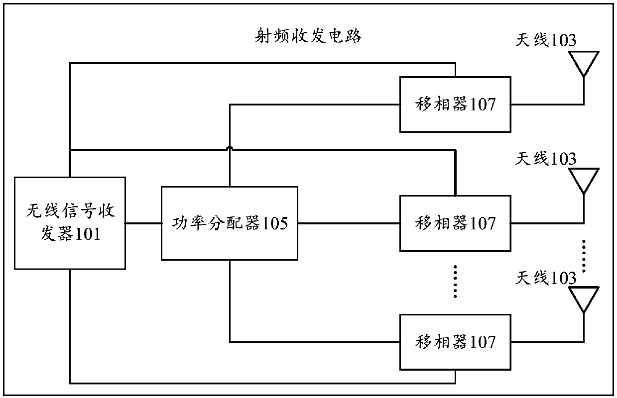
[0035] see figure 1 As shown, the embodiment of the present application provides a radio frequency transceiver circuit, including:
[0036] Wireless signal transceiver 101;
[0037] multiple antennas 103;
[0038] The power divider 105 includes a first power dividing port and a plurality of second power dividing ports, wherein the first power dividing port is connected to the wireless signal transceiver 101;
[0039] A plurality of phase shifters 107, in a plurality of phase shifters 107, the first phase shift port of each phase shifter 107 is connected with a plurality of second power division ports of the power divider 105 in one-to-one correspondence, each phase shifter 107 The second phase shift ports are all connected to the wireless signal transceiver 101 , and the third phase shift ports of each phase shifter 107 are connected to the plurality of antennas 103 in one-to-one correspondence.
[0040] It can be understood that, through the power distributor 105 in the ra...
Embodiment 2
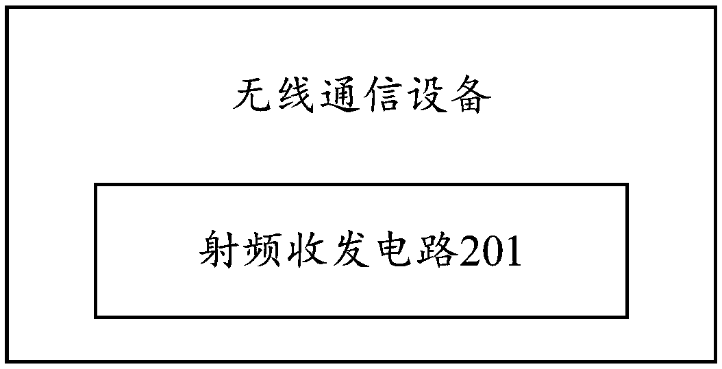
[0051] see figure 2 As shown, the embodiment of the present application provides a wireless communication device, including a radio frequency transceiver circuit 201, and the radio frequency transceiver circuit 201 is the radio frequency transceiver circuit described in Embodiment 1 above.
[0052] Due to the adoption of the radio frequency transceiver circuit described in the previous embodiment of the present application, the wireless communication device can reduce the coverage blind spots of wireless signals through the setting of multiple antennas, and solve the problem that some There is a problem of receiving and sending blind spots in the direction, so that the directionality of the wireless communication device is better when receiving and sending wireless signals, and by setting multiple phase shifters corresponding to multiple antennas one by one, it is possible to improve the transmission and reception of the wireless communication device. The purpose of the signa...
Embodiment 3
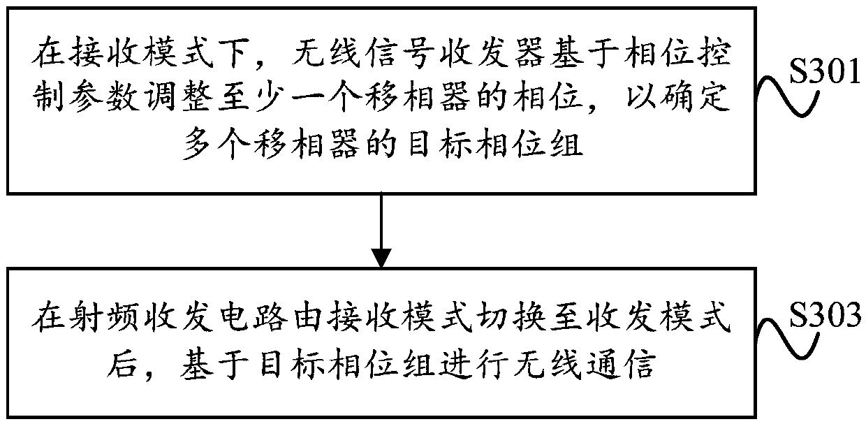
[0056] see image 3 , the embodiment of the present application provides a wireless communication method, which is applied to the radio frequency transceiver circuit described in the above embodiment, and the wireless communication method may include the following process steps:
[0057] S301. In a receiving mode, the wireless signal transceiver adjusts the phase of at least one phase shifter based on a phase control parameter, so as to determine a target phase group of multiple phase shifters.
[0058] S303. After the radio frequency transceiver circuit switches from the receiving mode to the transmitting and receiving mode, perform wireless communication based on the target phase group.
[0059] Wherein, the target complete machine signal corresponding to the target phase group satisfies the preset condition; the target complete machine signal is shifted by the power divider based on the target phase group for the wireless signals received by multiple antennas based on the m...
PUM
 Abstract
Description
Claims
Application Information
 - Generate Ideas
- Intellectual Property
- Life Sciences
- Materials
- Tech Scout
- Unparalleled Data Quality
- Higher Quality Content
- 60% Fewer Hallucinations
Browse by: Latest US Patents, China's latest patents, Technical Efficacy Thesaurus, Application Domain, Technology Topic, Popular Technical Reports.
© 2025 PatSnap. All rights reserved.Legal|Privacy policy|Modern Slavery Act Transparency Statement|Sitemap|About US| Contact US: help@patsnap.com


