
Oil-water separation type fryer

A technology of oil-water separation and deep fryer, which is applied to the utensils for frying things in oil, household utensils, applications, etc., which can solve the problems of high use cost, unfavorable long-term use of edible oil, and large amount of edible oil, etc., to achieve The effect of many times of use, convenient installation and long use time

Pending Publication Date: 2020-06-23
陈开领
View PDF0 Cites 0 Cited by
  • Summary
  • Abstract
  • Description
  • Claims
  • Application Information

AI Technical Summary

Problems solved by technology

[0004] In view of this, the object of the present invention is to provide an oil-water separation type fryer to solve the problem that the fryer in the prior art is not conducive to the long-term use of edible oil, the amount of edible oil consumed once used is large, and the use cost is relatively high. high technical issues

Method used


Image

  • Oil-water separation type fryer
  • Oil-water separation type fryer
  • Oil-water separation type fryer

Examples


Embodiment 1

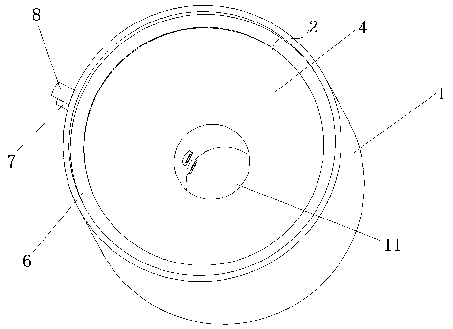
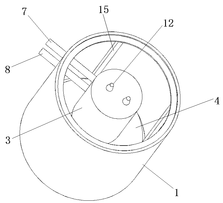
[0039] Such as Figure 1 to Figure 7 As shown, the oil-water separation fryer is made of stainless steel and includes a cylindrical shell 1 with a hollow structure. The inner wall of the shell 1 is evenly welded with vertical beams extending axially along the circumference of the shell 1. 15 (reference figure 2 and Figure 5 ), the vertical beam 15 is a rectangular tube.

[0040] The housing 1 is provided with a pot liner 2, such as figure 1 , figure 2 , image 3 and Figure 5 As shown, the inner pot 2 is composed of two parts, namely a pot body 4 and a cylinder body 3 connected to the bottom of the pot body 4 . Wherein, the inner surface of the pot body 4 is a circular arc surface, which is closed from top to bottom, with the largest diameter at the top and the smallest inner diameter at the bottom. Seen from the figure, the top opening edge of the pot body 4 is integrally formed with a circle of turning edge 6 extending radially of the pot body 4, and the turning ed...

Embodiment 2

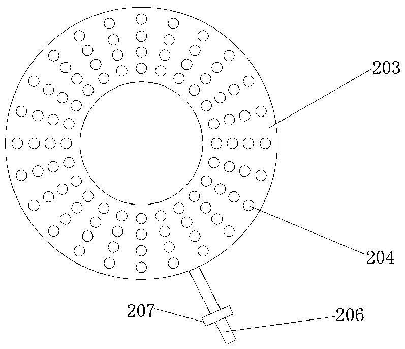
[0051] Such as Figure 8 and Figure 9 As shown, the difference between this embodiment and the above-mentioned embodiment 1 is that in this embodiment, the heating assembly is a liquefied gas heating assembly, and the liquefied gas heating assembly is a stove plate 203. Avoid the escape hole of the cylinder body, the cylinder body passes through the avoidance hole so that the stove plate 203 is sleeved outside the cylinder body 201, and is located under the pot body 202, and the stove plate 203 is provided with an air inlet pipe communicating with the liquefied gas source 206 , the inlet pipe 206 is provided with an inlet valve 207 for controlling on-off of the liquefied gas, and the valve 207 is located outside the casing 205 . The upper part of the stove 203 is provided with fire outlets 204 distributed in a circle, and the casing 205 is provided with an ignition switch (not shown in the figure) for controlling the switch of the stove 203, and turning the ignition switch c...

Embodiment 3

[0054] The difference between this embodiment and the above-mentioned embodiment 1 is that in this embodiment, the inner surface of the pot body is a conical surface.


PUM


Abstract

The invention relates to an oil-water separation type fryer which comprises a shell, a fryer container, a heating assembly and a filter screen, and the shell is of a hollow structure; the cooker container is fixed in the shell and comprises a cooker body and a barrel connected to the bottom of the cooker body, the inner surface of the cooker body is an arc surface or a conical surface and is closed up from top to bottom, a turned edge extending outwards in the radial direction of the cooker body is arranged at the top of the cooker body, an opening is formed in the bottom of the cooker body, and the barrel is connected to the opening and is coaxial with the shell; the heating assembly is an electric heating assembly or a liquefied gas heating assembly and is used for heating the edible oil; the filter screen is arranged in the pot body and is used for filtering food residues; when the fryer is used, water is firstly added into the pot container, and then edible oil is added, so that the oil-water separation surface is positioned below the opening. Compared with an existing fryer, the oil-water separation type fryer saves more oil and more energy.

Description

technical field [0001] The invention relates to the field of food processing machinery, in particular to an oil-water separation type fryer. Background technique [0002] Fryer refers to kitchen equipment that uses edible oil as the main raw material to fry and cook food. It has the characteristics of reasonable structure, simple operation, fast heating speed, and easy cleaning. It is widely used by fast food restaurants, hotels, and catering companies. Applied kitchen equipment. [0003] When the fryer in the prior art is frying food, the food residues produced cannot be separated from the oil, and these residues will turn black and zoom when they are fried continuously at high temperature for a long time, and stick to the bottom of the fryer, resulting in Strong carcinogens and other substances harmful to health. Mixing cooking oil with food residues will cause the cooking oil to change color and deteriorate, which is not conducive to the long-term use of cooking oil, and...

Claims


Application Information

Patent Timeline
IPC IPC(8): A47J37/12
CPCA47J37/1242A47J37/1257A47J37/1261A47J37/1276
Inventor 陈开领陈士礼
Owner 陈开领
Learn More