
Stamping die for computer keyboard

A technology for stamping dies and computer keyboards, applied in the field of stamping dies for computer keyboards, can solve problems such as difficulty in demolding, position deviation, and difficulty in taking out, and achieve the effects of avoiding the quality of stamping products, reducing demoulding damage, and uniform thrust force.

Inactive Publication Date: 2020-06-19
苏州淏源精密科技有限公司
View PDF4 Cites 3 Cited by
  • Summary
  • Abstract
  • Description
  • Claims
  • Application Information

AI Technical Summary

Problems solved by technology

However, the existing stamping dies have the problem of difficult demoulding. Because the surface of the keyboard is a concave arc structure, after the stamping is completed, the keyboard is easily embedded in the stamping groove and it is difficult to take it out; in addition, the stamping die is easily affected by external force The position of the impact is shifted, causing the stamping quality of the keyboard to be affected

Method used


Image

  • Stamping die for computer keyboard
  • Stamping die for computer keyboard
  • Stamping die for computer keyboard

Examples


Embodiment

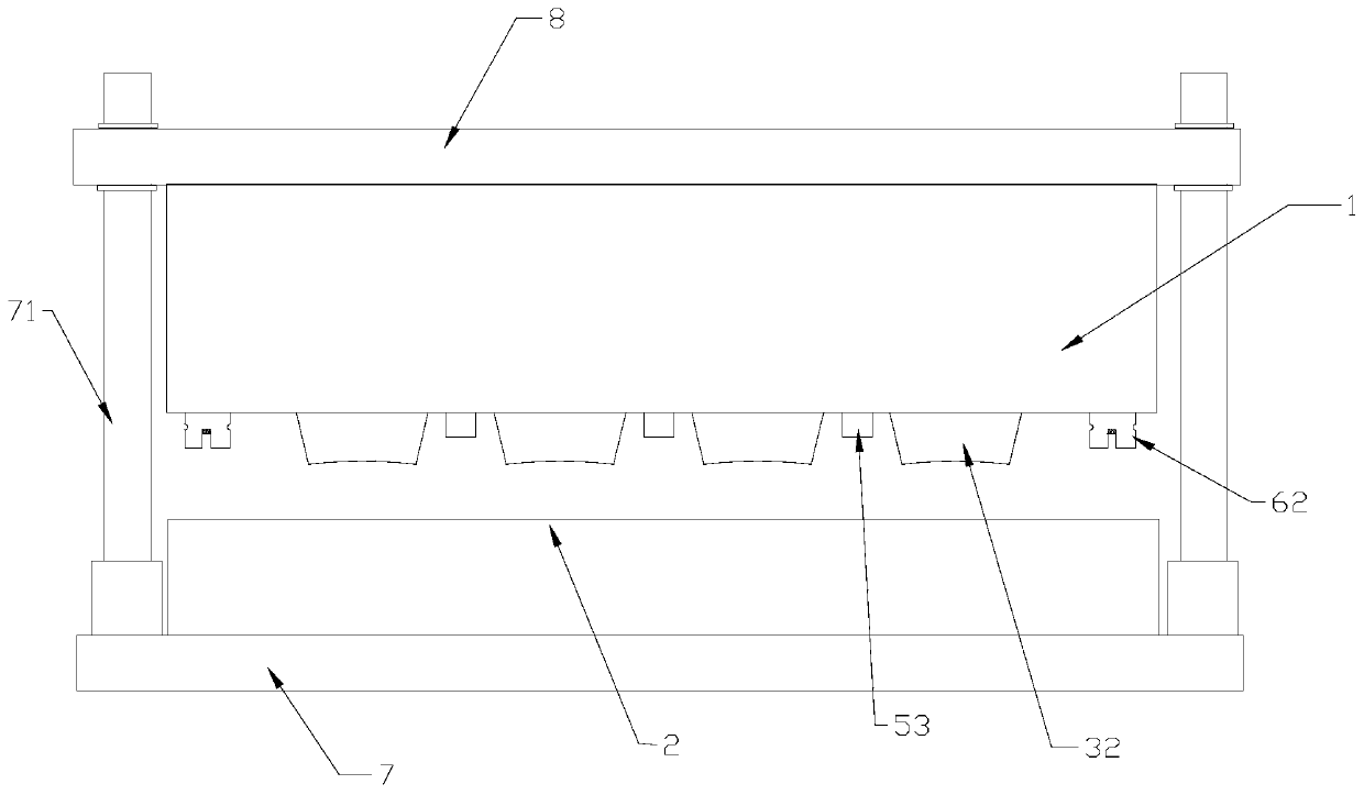
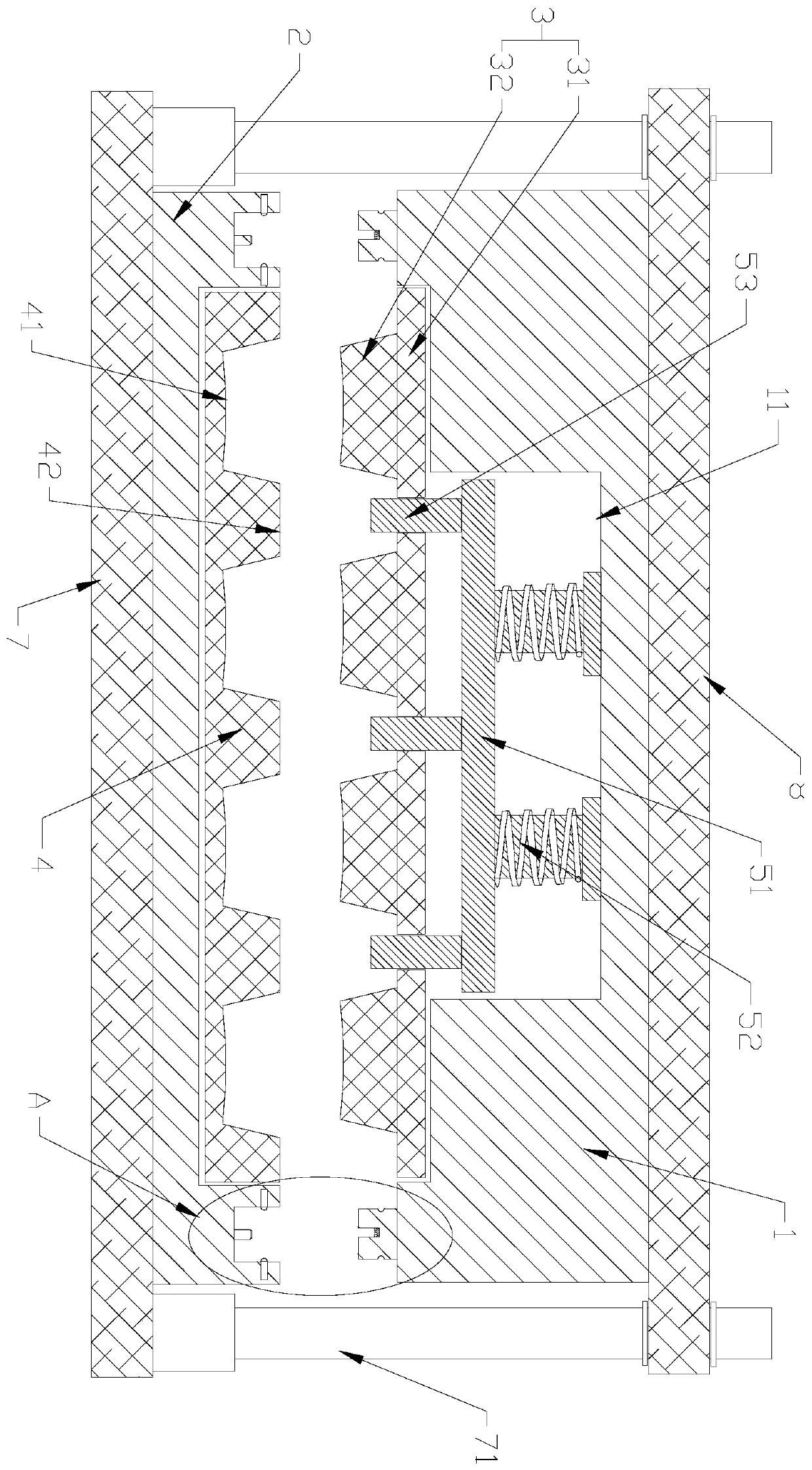
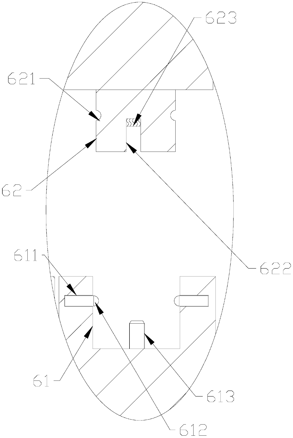
[0022] See attached Figure 1-2 As shown, a kind of stamping mold that is used for computer keyboard of the present invention comprises upper formwork 1, lower formwork 2 that are arranged oppositely, upper mold core 3 is installed on described upper formwork 1, and described lower formwork 2 is installed with The lower mold core 4 matched with the upper mold core 3 . The upper mold core 3 includes an upper mold core plate 31 , and a plurality of punching protrusions 32 matching the shape of the keyboard key grid are provided at the lower end of the upper mold core plate 31 . The upper mold plate 1 is provided with a groove 11 located at the upper end of the upper mold core plate 31 , and a push assembly for easy demoulding is arranged in the groove 11 . The push assembly includes a push plate 51 that can move up and down. The upper end of the push plate 51 is connected to the spring set 52 fixed in the groove 11, and the lower end is provided with a plurality of movable The...


PUM


Abstract

The invention discloses a stamping die for a computer keyboard. The stamping die comprises an upper die plate and a lower die plate which are oppositely arranged, wherein an upper die core is installed on the upper die plate, a lower die core is installed on the lower die plate, the upper die core comprises an upper die core plate, a plurality of stamping protruding blocks matched with keyboard keys in shape are arranged at the lower end of the upper die core plate, a groove located in the upper end of the upper die core plate is formed in the upper die plate, a pushing assembly is arranged inthe groove, the pushing assembly comprises a pushing plate capable of moving up and down, the upper end of the pushing plate is connected with a spring set fixedly connected into the groove, a plurality of pushing protruding columns movably arranged on the upper die core plate in a penetrating mode are arranged at the lower end of the pushing plate, the corresponding pushing protruding column islocated between every two adjacent stamping protruding blocks, and a limiting assembly for preventing the upper die core and the lower die core from deviating during die assembly is further arranged between the upper die plate and the lower die plate. According to the stamping die, a stamped finished product can be conveniently taken out, and the quality problem of the stamped finished product caused by die assembly position deviation is avoided.

Description

technical field [0001] The invention relates to the technical field of computer accessories production equipment, in particular to a stamping die for computer keyboards. Background technique [0002] Stamping die is a special process equipment that processes materials (metal or non-metal) into parts (or semi-finished products) in stamping processing, and becomes a cold stamping die (commonly known as a cold stamping die). Stamping is a pressure processing method that uses a mold installed on a press to apply pressure to the material at room temperature to cause separation or plastic deformation to obtain the required parts. The quality, production efficiency and production cost of stamping parts are directly related to the design and manufacture of stamping dies. [0003] Stamping dies are also used in the production process of computer keyboards, and the stamping process of the keyboard is used to complete the stamping and forming of the keyboard. However, the existing st...

Claims


Application Information

Patent Timeline
Patent Type & Authority Applications(China)
IPC IPC(8): B29C51/30B29C51/38B29C51/44
CPCB29C51/30B29C51/38B29C51/44
Inventor 赵正
Owner 苏州淏源精密科技有限公司
Learn More