
High-precision high-rigidity turning and milling combined center inclined lathe bed

A compound center and high rigidity technology, applied in the direction of large fixed members, metal processing machinery parts, maintenance and safety accessories, etc., can solve the problems of low chip removal efficiency and slow chip removal speed, and achieve high chip removal efficiency and easy removal Effects of chipping, low notch sensitivity

Pending Publication Date: 2020-06-19
BEIJING PROSPER PRECISION MACHINE TOOL CO LTD
View PDF0 Cites 2 Cited by
  • Summary
  • Abstract
  • Description
  • Claims
  • Application Information

AI Technical Summary

Problems solved by technology

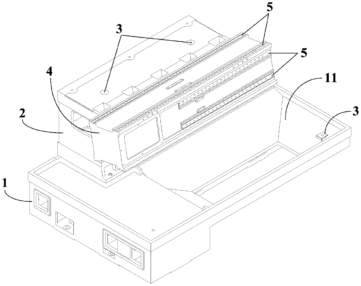
[0005] In view of this, in order to solve the technical problems such as slow chip removal speed and low chip removal efficiency of the turning-milling compound center in the prior art, the present invention provides a method that can avoid chip accumulation and achieve effective chip removal, thereby improving the operating speed of the machine tool and reducing the chip removal efficiency. High-precision and high-rigidity turning-milling compound center inclined bed for machine tool work efficiency

Method used


Image

  • High-precision high-rigidity turning and milling combined center inclined lathe bed
  • High-precision high-rigidity turning and milling combined center inclined lathe bed
  • High-precision high-rigidity turning and milling combined center inclined lathe bed

Examples


Embodiment Construction

[0034] Embodiments of the present invention are described in detail below, examples of which are shown in the drawings, wherein the same or similar reference numerals designate the same or similar elements or elements having the same or similar functions throughout. The embodiments described below by referring to the figures are exemplary and are intended to explain the present invention and should not be construed as limiting the present invention.

[0035] In describing the present invention, it is to be understood that the terms "upper", "lower", "front", "rear", "left", "right", "vertical", "horizontal", "top", The orientation or positional relationship indicated by "bottom", "inner", "outer", etc. is based on the orientation or positional relationship shown in the drawings, and is only for the convenience of describing the present invention and simplifying the description, rather than indicating or implying the referred device or positional relationship. Elements must hav...


PUM

PropertyMeasurementUnit
Angleaaaaaaaaaa
Depthaaaaaaaaaa
Angleaaaaaaaaaa

Abstract

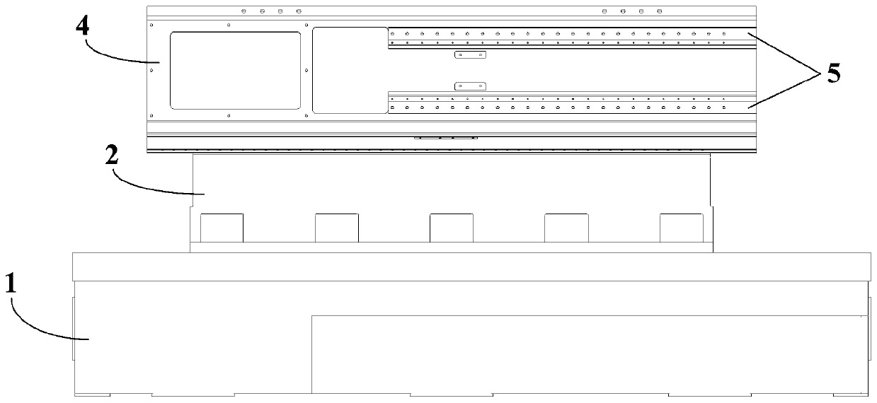
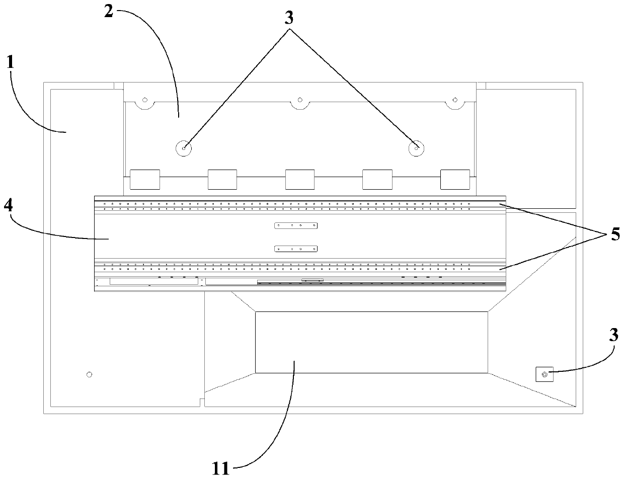
The invention discloses a high-precision high-rigidity turning and milling combined center inclined lathe bed. The high-precision high-rigidity turning and milling combined center inclined lathe bed comprises a base and a stand column, wherein the stand column is fixed to one side of the top of the base, the outer side wall of the stand column is perpendicularly fixed to the base, the inner side wall of the stand column is obliquely fixed to the base, and the included angle between the inner side wall of the stand column and the top end face of the base ranges from 75 degrees to 85 degrees. According to the turning and milling combined center inclined lathe bed, by means of the inclined side wall of the stand column, chippings generated after a workpiece is machined by a turning and milling combined center can be discharged in time through a lathe bed structure, and the chippings are better and faster discharged by means of the inclination angle of the side wall of the stand column compared with a common vertical angle or a common horizontal angle, therefore, the situation that the chippings are accumulated in a machine tool and then the operation of the machine tool is influencedis avoided, the chipping removal efficiency is improved, moreover, the overall working efficiency of the machine tool is further improved, and high practicability is achieved.

Description

technical field [0001] The invention relates to the technical field of machine tool processing equipment, and more specifically relates to a high-precision and high-rigidity turning-milling composite center inclined bed. Background technique [0002] As a strategic industry related to the national defense security and the healthy development of the national economy, the development level of the machine tool industry is an important symbol of a country's comprehensive national strength and industrial modernization. At present, in order to improve the processing accuracy and processing efficiency, the existing domestic turning-milling compound machining centers often work hard on the processing mechanism. However, as everyone knows, the rationality of the machine bed structure design is also extremely critical. [0003] The bed structure of the existing turning-milling compound center is mostly installed in the vertical and horizontal directions. However, during the specific u...

Claims


Application Information

Patent Timeline
IPC IPC(8): B23Q1/01B23Q11/00
CPCB23Q1/015B23Q11/0042
Inventor 吴行飞吴道涵邓崛华许宇亮孙立业
Owner BEIJING PROSPER PRECISION MACHINE TOOL CO LTD
Learn More