
Method for rapidly detecting quality of conductive plate strip

A conductive plate and quality technology, applied in the direction of measuring electrical variables, measuring electricity, measuring devices, etc., can solve the problems of inability to detect surface roughness, difficult to move strip detection, and not involving signal acquisition and analysis systems, etc.

Inactive Publication Date: 2020-06-16
CENT SOUTH UNIV
View PDF7 Cites 0 Cited by
  • Summary
  • Abstract
  • Description
  • Claims
  • Application Information

AI Technical Summary

Problems solved by technology

At present, the most widely used on-line detection methods for conductive strip defects are: infrared detection method, magnetic flux leakage detection method and image-based surface quality detection method, but there are application limitations: the maximum detection depth of infrared detection method is only 1mm, and the data Large fluctuations; the application range of the magnetic flux leakage detection method is limited to magnetic substances such as iron, cobalt, and nickel, and it cannot detect non-magnetic substances such as copper, magnesium, and aluminum, and the ability to classify and identify defects is poor, and the surface roughness cannot be detected. Measurement accuracy is easily affected by the environment
The image-based surface quality inspection method can accurately detect the surface defects of the conductive strip, but cannot detect the conductive strip with internal defects
At the same time, most of the detection devices of the above detection methods are placed statically, or are inconvenient to move due to the limitation of the device structure, and are not suitable for the detection of difficult-to-move strips
In addition, high-temperature environments are often involved in production, and the above-mentioned detection methods are difficult to achieve online continuous high-temperature detection
In the patent 201310530795.2, a resistance testing device is used, which can measure the change of sample resistance in a variable temperature environment, but the patent does not involve signal acquisition and analysis systems, and the measured area is fixed, which cannot realize the test sample in space and continuous measurement over time

Method used


Image

  • Method for rapidly detecting quality of conductive plate strip
  • Method for rapidly detecting quality of conductive plate strip
  • Method for rapidly detecting quality of conductive plate strip

Examples


Embodiment 1

[0060] Test material: carbon tool steel saw blade, with a section of about 0.61mm×11.35mm and a length of about 315mm;

[0061] Binding post interval / information collection area length: 30mm;

[0062] Input constant current: 0.2A;

[0063] Movement mode: the detection device is stationary, and the sample moves;

[0064] Sample movement speed: 50mm / s;

[0065] Signal acquisition frequency: 50 times / s;

[0066] Standard resistivity: 8.190×10 -7 Ω·m;

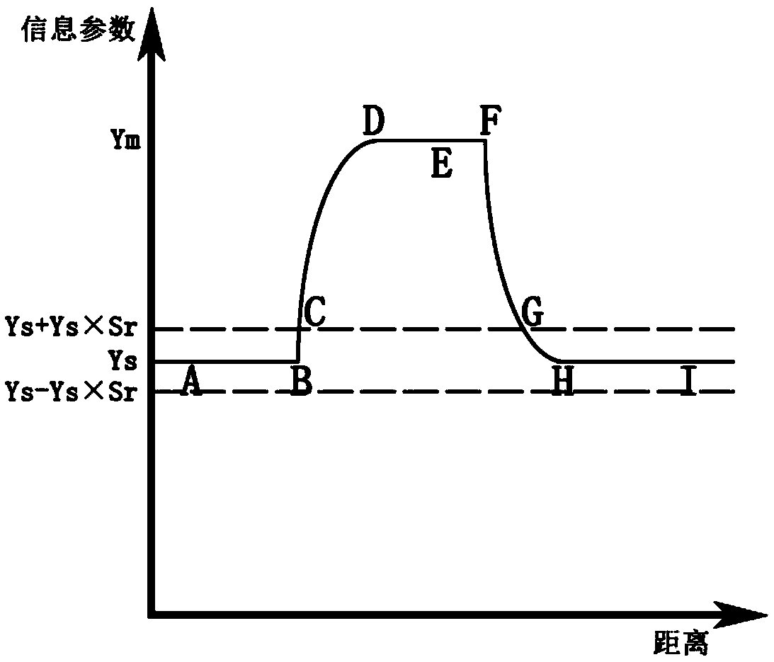
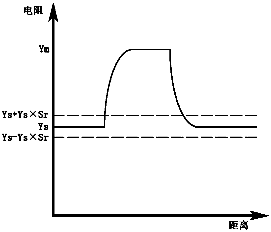
[0067] Figure 6 is the actual resistivity signal-distance curve, S r =0.00733, according to |actual resistivity-standard resistivity| / standard resistivity≥S r , it is determined that there is one defect, and the resistivity within the position range of 193mm-195mm increases abnormally, and the corresponding defect enters the information collection area, Y m =8.306×10 -7 Ω·m, the resistivity returns to normal within the range of 223mm-225mm, and the corresponding defect leaves the information collection area. The distances...

Embodiment 2

[0069] Testing material: aluminum alloy plate, about 800mm in length, 84mm×2mm in section;

[0070] Binding post interval / information collection area length: 70mm;

[0071] Input constant current: 1.2A;

[0072] Movement mode: the detection device is stationary, and the sample moves;

[0073] Sample movement speed: 15mm / s;

[0074] Signal collection frequency: 30 times / s;

[0075] Standard conductivity: 56.0%IACS;

[0076] Figure 8 is the actual conductivity-distance curve, S r =0.017, according to |actual conductivity-standard conductivity| / standard conductivity≥S r , it is determined that there is one defect, the conductivity within the range of 475mm-490mm decreases abnormally, and the corresponding defect enters the information collection area, Y m =51.0%IACS, the electrical conductivity returns to normal within the range of 545mm-560mm, and the corresponding defect leaves the information collection area. The distances between the start point and end point of the d...

Embodiment 3

[0078] Testing material: conductive tape, thickness 0.09mm, width 20mm, length about 2000mm, Figure 10 The physical picture of the test sample;

[0079] Binding post interval / information collection area length: 100mm;

[0080] Input constant current: 1.0A;

[0081] Movement mode: the detection device is stationary, and the sample moves;

[0082] Sample movement speed: 50mm / s

[0083] Signal acquisition frequency: 60 times / s

[0084] Standard voltage: 12.95mV;

[0085] Figure 11 is the measured voltage signal-distance curve, S r =0.004, according to|actually measured voltage signal-standard voltage signal| / standard voltage signal≥S r , it is determined that there is one defect, the voltage within the range of 430mm-478mm increases abnormally, and the corresponding defect enters the information collection area, Y m =13.62mV, the voltage returns to normal within the position range of 530mm-578mm, the corresponding defect leaves the information collection area, the dista...


PUM

PropertyMeasurementUnit
areaaaaaaaaaaa
thicknessaaaaaaaaaa
lengthaaaaaaaaaa

Abstract

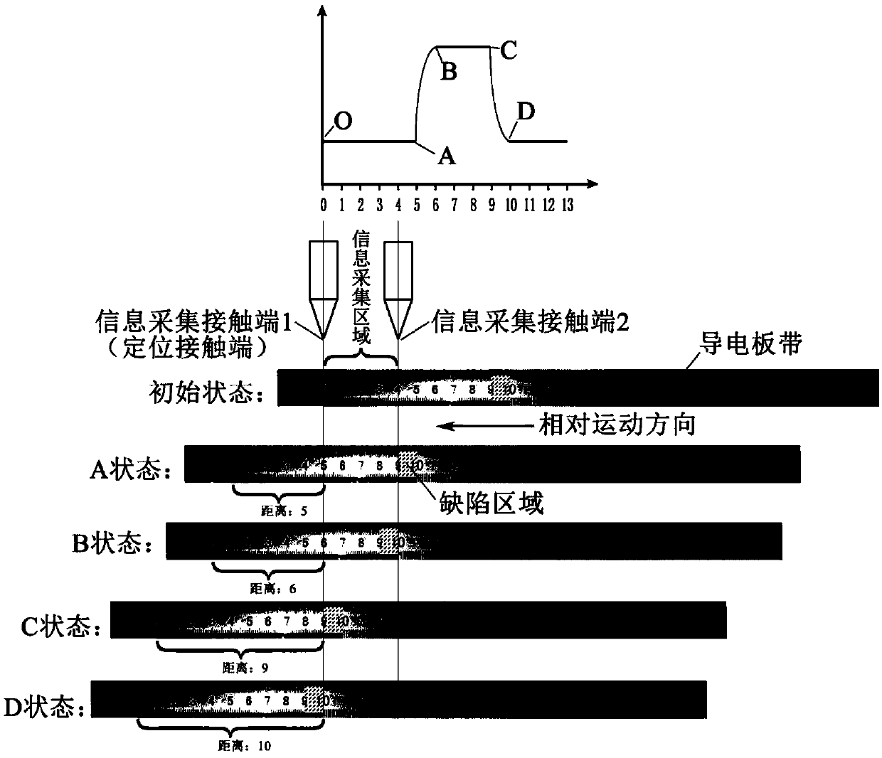
The invention relates to a method for rapidly detecting quality of a conductive plate strip, and belongs to the technical field of rapid quality detection. The method comprises the following steps: during detection, making a detection device and the conductive plate strip move relatively, and judging the quality of the detected conductive plate strip by continuously collecting information and calculating information parameters, wherein the information includes but is not limited to a voltage, a current and a position, the information is continuous information, and the information parameters are selected from at least one of a resistance, resistivity, electric conductivity, conductivity and the voltage; comparing the obtained actual information parameters with standard information parameters; and when |the actual information parameter-the standard information parameter| / the standard information parameter is greater than or equal to a defect judgment threshold value, judging that a defect exists in a region corresponding to the actual information parameters, and judging that the quality of the region corresponding to the actual information parameters is qualified when |the actual information parameter-the standard information parameter| / the standard information parameter is less than the defect judgment threshold.

Description

technical field [0001] The invention relates to a method for rapidly detecting the quality of conductive strips, which belongs to the technical field of rapid quality detection, in particular to the technical field of rapid quality detection of conductive materials. Background technique [0002] In modern society, the requirements for the quality of strip products are constantly increasing. However, due to the lack of an efficient online detection and monitoring system, the product quality is not guaranteed. Establishing an online information collection and detection system in the production process, and improving the quality of strip production through sensitive information feedback and precise production process control have always been a matter of great concern to our country's scientific and technological workers, technicians and production enterprises. At present, the most widely used on-line detection methods for conductive strip defects are: infrared detection method,...

Claims


Application Information

Patent Timeline
Patent Type & Authority Applications(China)
IPC IPC(8): G01R31/28
CPCG01R31/2836
Inventor 李红英赵辉
Owner CENT SOUTH UNIV
Learn More