
Conveying belt tearing detection system and method based on AI intelligent analysis

A technology of intelligent analysis and conveying belts, which is applied in the direction of material analysis, image analysis, and material analysis through optical means, can solve the problems of personnel injury economy, equipment damage, intrusion, etc., to reduce accident losses, improve work efficiency, and speed up speed effect

Active Publication Date: 2020-06-16
瑞思特(珠海)科技有限责任公司 +1
View PDF7 Cites 4 Cited by
  • Summary
  • Abstract
  • Description
  • Claims
  • Application Information

AI Technical Summary

Problems solved by technology

The conveyor belt is an important part of the belt conveyor, and its cost accounts for more than 40% of the whole machine. However, the belt tear failure of the belt conveyor has been plagued by every enterprise, especially in bulk cargo terminals, mines, metallurgy, and power plants. In large-scale enterprises such as China, accidents of belt tearing occur from time to time. Once a conveyor belt worth hundreds of thousands or even tens of millions is torn longitudinally, raw materials such as ore and slag will invade the mechanical system of the equipment through the tear opening, causing equipment damage. , and even cause major accidents such as personal injury and huge economic losses. Therefore, it is necessary to use AI intelligent analysis terminal technology to detect and identify the tearing state of the belt in real time, and immediately discover and solve hidden dangers in production safety. Emergency alarms and braking equipment , Repair and replace the belt to ensure the safe operation of production

Method used


Image

  • Conveying belt tearing detection system and method based on AI intelligent analysis
  • Conveying belt tearing detection system and method based on AI intelligent analysis
  • Conveying belt tearing detection system and method based on AI intelligent analysis

Examples


Embodiment Construction

[0027] The specific embodiments of the present invention will be described in detail below in conjunction with the accompanying drawings.

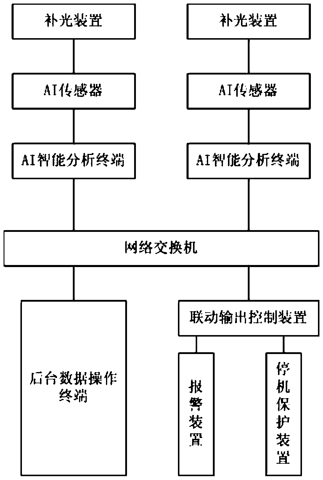
[0028] A conveyor belt tear detection system based on AI intelligent analysis, such as figure 1 , is characterized in that it includes a supplementary light, an AI sensor, an AI intelligent analysis terminal, a network switch, a background data operation terminal, a linkage output control device, an alarm device, and a shutdown protection device. There are two analysis terminals, which are respectively distributed on the left and right sides of the conveyor belt and run side by side. The AI ​​intelligent analysis terminal and the linkage output control device are connected to the network using optical fiber or WIFI, and communicate with the background data operation terminal through the network, and the linkage output control device is connected to the alarm. Equipment and downtime protection devices, AI intelligent analysis terminals and ...


PUM


Abstract

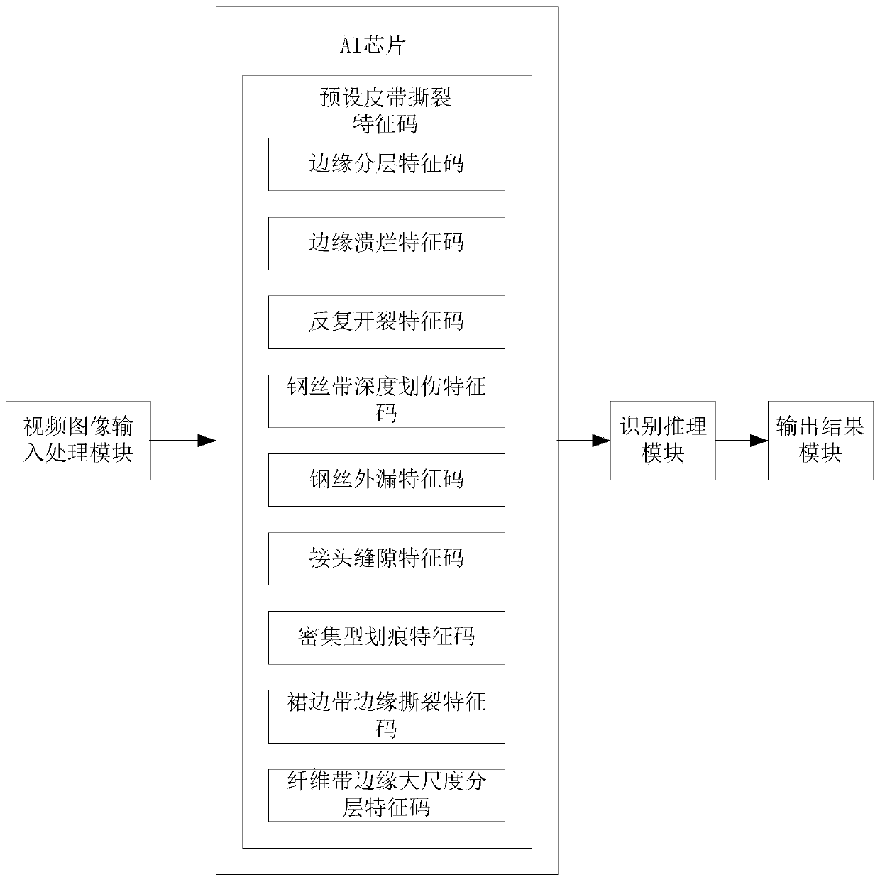
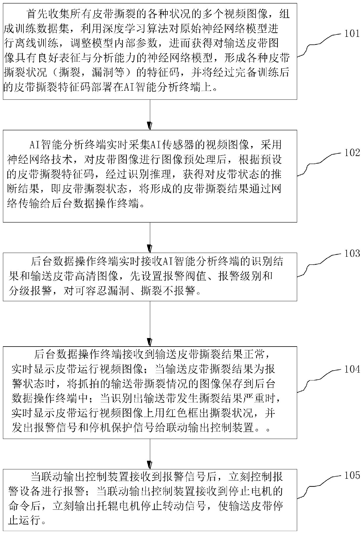
The invention relates to a conveying belt tearing detection system and a conveying belt tearing detection method based on AI intelligent analysis. The conveying belt tearing detection system comprisesa light supplementing lamp, an AI sensor, an AI intelligent analysis terminal, a network switch, a background data operation terminal, a linkage output control device, alarm equipment and a shutdownprotection device. The conveying belt tearing detection method comprises the steps of: forming a belt tearing feature code through offline training and learning; deploying the belt tearing feature code to the AI intelligent analysis terminal; acquiring a video image of the AI sensor by means of the AI intelligent analysis terminal in real time; and adopting a neural network learning method to judge the length and the width of a belt crack accurately. When the belt is torn off, a shutdown protection signal and an alarm signal can be output within the shortest time, the linkage output control device is controlled according to a belt tearing detection result, the alarm signal and the shutdown protection signal are output, remote real-time protection and monitoring of the state of the conveying belt are achieved, operators in an operation room can track the production and operation dynamic state, the measurement precision is high, misoperation is avoided, and equipment linkage is facilitated.

Description

technical field [0001] The invention belongs to a new technological breakthrough in the field of conveyor belt state detection, and relates to artificial intelligence (AI for short) intelligent analysis conveyor belt tear detection system and detection method. Background technique [0002] Belt conveyor is one of the continuous conveying equipment used by many enterprises. It is widely used in metallurgy, mineral processing, petroleum, chemical industry, light industry, building materials, steel mills, ports and other fields, and is increasingly moving towards high speed, large scale, super development in the long-distance direction. The conveyor belt is an important part of the belt conveyor, and its cost accounts for more than 40% of the whole machine. However, the belt tearing failure of the belt conveyor has been plagued by every enterprise, especially in bulk cargo terminals, mines, metallurgy, and power plants. In large-scale enterprises such as China, accidents of be...

Claims


Application Information

Patent Timeline
Patent Type & Authority Applications(China)
IPC IPC(8): G01N21/89G01B11/02G01B11/04G06T7/00
CPCG01N21/8901G01N21/8914G01B11/022G01B11/043G01B11/046G01B11/028G06T7/0004G06T2207/10016G06T2207/20081G06T2207/20084G01N2021/8908B65G43/02B65G15/00Y02P90/30
Inventor 马鑫马刚黄守柱
Owner 瑞思特(珠海)科技有限责任公司
Learn More