


Quick Research
Generate reliable direction feasibility study reports for your R&D in just a few steps.

Technical Q&A
Discover and master advanced knowledge NOW. Basics, ideas, possibilities, all at once.

Find Solutions
As an expert in R&D theories, this can generate solutions to your technical problems instantly.

Evaluate Feasibility
Analyze your overall solution with one click, know your potential R&D risks in advance.

Monitor Landscape
Get weekly tech updates, stay abreast of the latest tech innovations and key insights.
Hydraulic pump convenient to install and assemble
A hydraulic pump and mounting plate technology, applied in the field of hydraulic pumps, can solve the problems of time-consuming replacement or maintenance, inconvenient installation and disassembly, and limited flexibility, and achieve the effects of convenient and flexible lifting and steering, convenient disassembly and assembly, and avoiding damage
- Summary
- Abstract
- Description
- Claims
- Application Information
AI Technical Summary
Problems solved by technology
Method used
Image


Examples
Embodiment 1
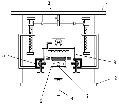
[0032] Wherein, lifting support device 4 comprises hydraulic cylinder 41, and hydraulic cylinder 41 is installed on the bottom of fixed plate 2, and the piston rod of hydraulic cylinder 41 penetrates upwards through fixed plate 2 and is rotatably sleeved with rotating seat 42, and the top of rotating seat 42 is fixed with support. plate 43.
[0033] Wherein, the piston rod of the hydraulic cylinder 41 is perpendicular to the fixed plate 2 , and the piston rod of the hydraulic cylinder 41 is rotatably connected to the rotating seat 42 through a bearing.
Embodiment 2
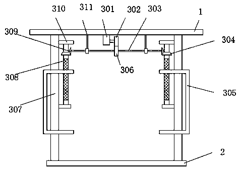
[0035] Wherein, the lifting adjustment device 3 includes a first motor 301, a guide post 307, and a support base 311, the first motor 301 is installed on the bottom of the first mounting plate 1, and the output shaft of the first motor 301 is fixedly sleeved with a first spur gear 302, two sets of support bases 311 are provided, and the two sets of support bases 311 are installed on the bottom of the first mounting plate 1. The two sets of support bases 311 are rotatably socketed with the same rotating shaft 303, and the rotating shaft 303 is fixedly sleeved with a second Spur gear 306, both ends of rotating shaft 303 are fixedly sleeved with first bevel gear 309, guide post 307 is provided with two, and two guide posts 307 are fixed between the first installation plate 1 and fixed plate 2, guide post 307 Two first fixed seats 310 are fixed on the sides of the two first fixed seats 310, and a first threaded rod 308 is rotatably connected between the two first fixed seats 310, a...
Embodiment 3
[0038]Wherein, the damping device 5 includes a mounting base 51, the mounting base 51 is fixed on the lifting base 305, the mounting base 51 is C-shaped, the inner top of the mounting base 51 is fixed with a slide bar 52, and the slide bar 52 is slidably sleeved with a slider 55, the upper and lower sides of the slider 55 on the sliding rod 52 are sleeved with springs 56, the bottom of the mounting base 51 is penetrated with a sleeve 54, and the mounting base 51 and the sleeve 54 are connected by threads, and the sleeve 54 is slidably sleeved On the slide bar 52 , the bottom end of the sleeve 54 is fixed with an arm bar 53 .
PUM
 Abstract
Description
Claims
Application Information
 - R&D Engineer
- R&D Manager
- IP Professional
- Industry Leading Data Capabilities
- Powerful AI technology
- Patent DNA Extraction
Browse by: Latest US Patents, China's latest patents, Technical Efficacy Thesaurus, Application Domain, Technology Topic, Popular Technical Reports.
© 2024 PatSnap. All rights reserved.Legal|Privacy policy|Modern Slavery Act Transparency Statement|Sitemap|About US| Contact US: help@patsnap.com