
Heart prosthesis valve

An artificial heart and prosthesis technology, applied in the field of medical devices, can solve problems such as adverse postoperative effects, reduce stent fatigue performance, affect cardiac contraction, etc., and achieve the effect of reducing the difficulty of grasping

Active Publication Date: 2020-06-12
UNIV OF SHANGHAI FOR SCI & TECH
View PDF10 Cites 3 Cited by
  • Summary
  • Abstract
  • Description
  • Claims
  • Application Information

AI Technical Summary

Problems solved by technology

If the subvalvular height of the artificial valve stent is too high, it will affect the original heart structure and heart function, cause chordae tendon rupture, touch the papillary muscle and other heart tissue abnormalities, and at the same time easily cause left ventricular outflow tract obstruction and induce adverse postoperative effects
[0017] 3. Traditional stents are integrated stents, mostly made of laser-cut pipes or wire braided. The overall material, wall thickness, and strength of the stents are roughly the same
When the stent is inserted into the heart, except for the key parts that play a supporting role, the mechanical properties of the remaining parts are too large, which will affect the contraction of the heart and reduce the fatigue performance of the stent

Method used


Image

  • Heart prosthesis valve
  • Heart prosthesis valve
  • Heart prosthesis valve

Examples


Embodiment 1

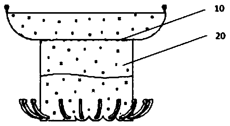
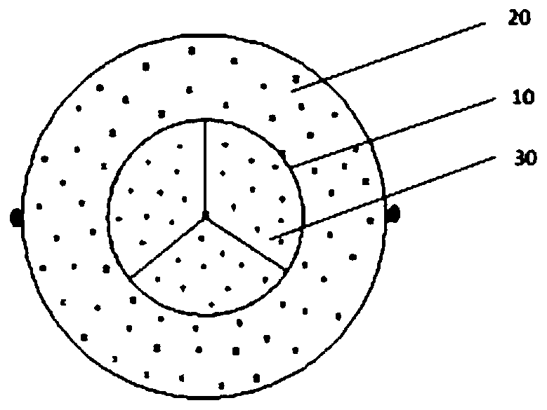
[0062] like figure 1 , figure 2 As shown, an interventional prosthetic heart valve includes a stent body 10 , a skirt 20 and a leaflet 30 .

[0063] Stent 10 (that is, the supporting and positioning structure of the prosthetic heart valve, used for bearing leaflets, attaching skirts, anchoring and positioning, etc.) is made of shape memory alloys, such as NiTi (nickel-titanium alloy), CuAlNi (copper-aluminum-nickel alloy) Wait. In this embodiment, NiTi is preferred.

[0064] The skirt 20 (that is, one or more layers of film attached to the inner surface or outer surface or both surfaces of the stent and has functions such as sealing and preventing paravalvular leakage) is made of polymer materials, such as PTFE (polytetrafluoroethylene), PET (polyethylene terephthalate), etc. The skirt 20 can also be made of biological tissue materials such as animal pericardium.

[0065] The valve leaflet 30 (i.e., the artificial valve leaflet, which is used to replace the original fail...

specific Embodiment approach

[0207] 1. Prosthetic valve loading process:

[0208] like Figure 20 As shown, the delivery device is basically composed of Tip head, traction rope, sheath tube, fixed ear and fixed head. In addition to the components shown in the figure, there are also conventional components such as manual or electric handles, catheters, and guide wires. This embodiment No elaboration on this.

[0209] ①The prosthetic valve was loaded in an ice-water bath below 5°C outside the body.

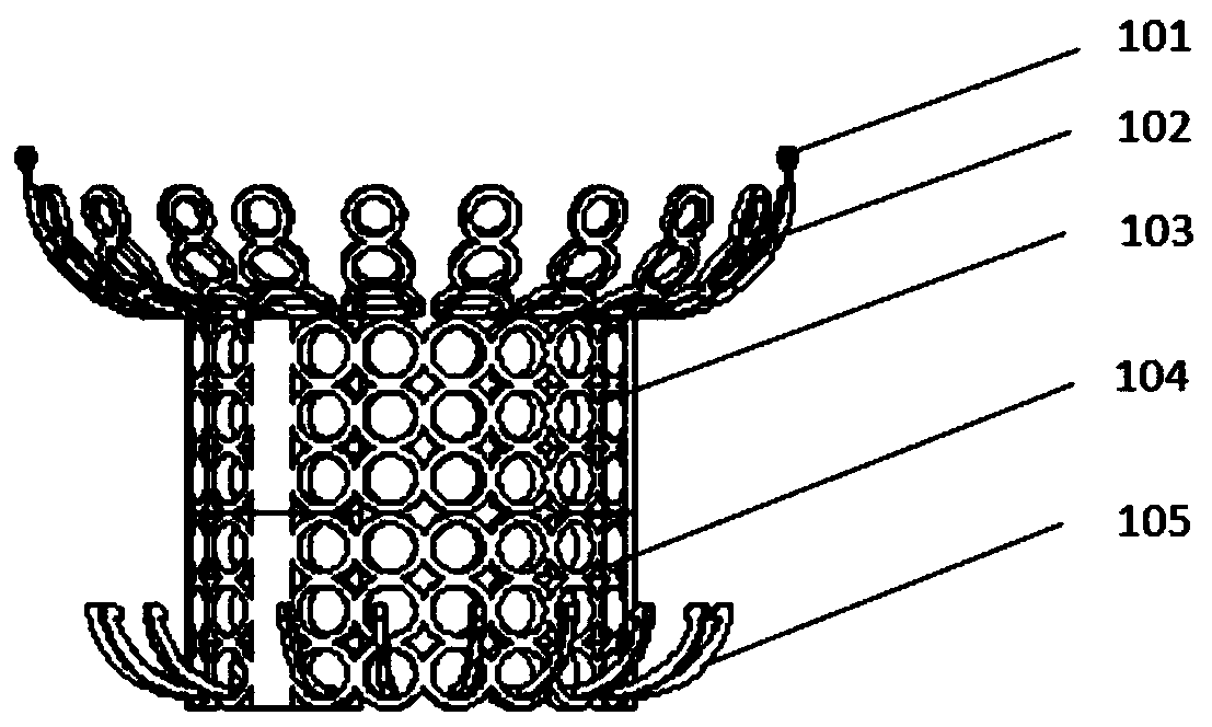
[0210] ② Connect the upper bracket 103 and the lower bracket 103 with the traction rope sent from the loading tool.

[0211] ③The prosthetic valve is compressed to a smaller size through a special loading tool and loading method, and then the fixed ear 101 is snapped into the fixed ear hole, and the prosthetic valve is completely wrapped in the sheath by pulling the fixed head.

[0212] ④ Fill the sheath with saline, etc., empty the air inside, and then push the sheath to fit the tip completely to achieve a ...

Embodiment 2

[0224] Other structures in this embodiment are the same as in Embodiment 1, except that the structures of the straight sleeve and straight rod are different from Embodiment 1.

[0225] The straight sleeve 2033 is provided with a T-shaped hollow area, and its cross section is T-shaped. The hollow inner wall of the straight sleeve 2033 is provided with a plurality of grooves at intervals. In the embodiment, the straight sleeve 2033 is a hollow columnar rod with a trapezoidal cross-section. The groove 20331 of the axis of the straight sleeve 2033, such as Figure 21 As shown, the groove 20331 is a groove in the hollow area of ​​the straight sleeve 2033 .

[0226] Preferably, the grooves 10331 are evenly and continuously distributed in all hollow areas of the straight sleeve 2033 .

[0227] The groove 20331 should be slightly larger than the buckle 20411 to complete mutual matching.

[0228] The straight rod 2041 is a columnar rod inserted in the two lower bracket walls 1042, a...


PUM


Abstract

A heart prosthesis valve comprises a stent body, a skirt edge and a plurality of valve leaflets, and the stent body comprises a separated movable stent and a plurality of claw lugs; the separated movable stent comprises an upper-layer stent, a lower-layer stent and a traction piece; the upper-layer stent comprises an upper-layer stent wall and a plurality of straight sleeves; the lower-layer stentis movably arranged at the lower part of the upper-layer stent, and comprises a lower-layer stent wall and a plurality of straight rods, the plurality of straight sleeves are respectively and vertically arranged on the wall of the upper-layer stent; a plurality of grooves are formed in the inner wall of the straight sleeve; the lower-layer stent wall is cylindrical; the plurality of straight rodsare vertically arranged on the lower-layer stent wall corresponding to the straight sleeves, and the upper ends of the straight rods are exposed out of the end part of the lower-layer stent wall; corresponding to the grooves, a plurality of protruding buckles are arranged on the outer wall of the upper ends of the straight rods, the lower-layer stent moves in the straight sleeves through the upper ends of the straight rods to achieve change of the distance between the end of the upper-layer stent and the claw lugs, and the lower-layer stent and the upper-layer stent are fixed through connection of the buckles and the grooves.

Description

technical field [0001] The invention belongs to the field of medical devices, in particular to an artificial heart prosthesis valve. Background technique [0002] The heart is the most important organ in the body of vertebrates. Its main function is to provide pressure for blood flow and to move blood to all parts of the body. The heart consists of four chambers, the left atrium, left ventricle, right atrium, and right ventricle. Both the left and right atria and the left and right ventricles are separated and do not communicate with each other. There are valves (atrioventricular valves) between the atrium and the ventricle. These valves have the function of "one-way valve", that is, through the "opening and closing movement", blood can only flow from the atrium to the ventricle, but not back. The valve between the left atrium and left ventricle is called the mitral valve, and the valve between the right atrium and right ventricle is called the tricuspid valve. (The valve...

Claims


Application Information

Patent Timeline
Patent Type & Authority Applications(China)
IPC IPC(8): A61F2/24
CPCA61F2/2412A61F2/2418A61F2/2436A61F2240/001
Inventor 冒鹏志王泽明石爱峰顾春玉沈景凤
Owner UNIV OF SHANGHAI FOR SCI & TECH
Learn More