Heat-preservation power life buoy

A lifebuoy and power technology, applied in the field of lifebuoy, can solve the problems of slow rescue, delay rescue work, accidents, etc., to achieve the effect of improving rescue speed, protecting drowning, and reducing possibility

Inactive Publication Date: 2017-02-08
珠海蓝创科技有限公司
View PDF13 Cites 10 Cited by
  • Summary
  • Abstract
  • Description
  • Claims
  • Application Information

AI Technical Summary

Problems solved by technology

[0004] Existing lifebuoys all need to be thrown manually. On the one hand, rescuers must rush to the scene of falling into the water. Rescue by one person who fell into the water needs to repeatedly move to the position of each person who fell into the water, and then throw the lifebuoys separately, resulting in slow rescue speed; As a result, the accuracy of lifebuoy throwing is extremely difficult to control, and because most of the drowning persons cannot swim, some drowning persons who can swim will also consume a lot of physical strength while waiting for rescue. Throw it to the side of the person who fell into the water, and the person who fell into the water will not be able to grasp the lifebuoy. Even if the rescuers have extra lifebuoys to re-throw, the rescue work will be greatly delayed.
In addition, the drowning person has been immersed in the water while waiting for rescue, and the temperature of the water is low. Soaking for a long time will easily take away a lot of heat from the human body, resulting in loss of physical strength, body stiffness, and listlessness. Under certain circumstances, the person who fell into the water may not be able to grasp the lifebuoy due to lack of physical strength or body stiffness, or even if he obtains the lifebuoy, an accident may occur due to the drop in body temperature and the continuous loss of heat.
In addition, the existing life buoys lack necessary lighting equipment. If the rescue site is at night or when the light is insufficient, it is difficult to meet the lighting needs of the lifeboat or the lighting equipment carried by rescuers alone, and it is extremely inconvenient to carry these lighting equipment.

Method used


Image

  • Heat-preservation power life buoy
  • Heat-preservation power life buoy
  • Heat-preservation power life buoy

Examples


Embodiment Construction

[0013] Such as Figure 1-5 shown.

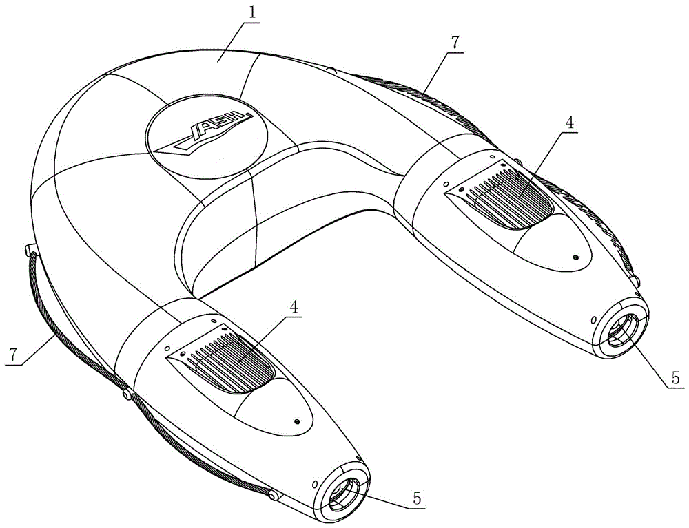
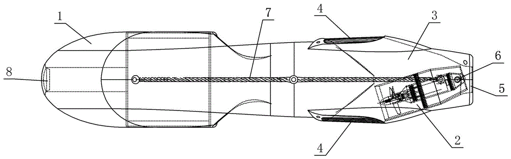
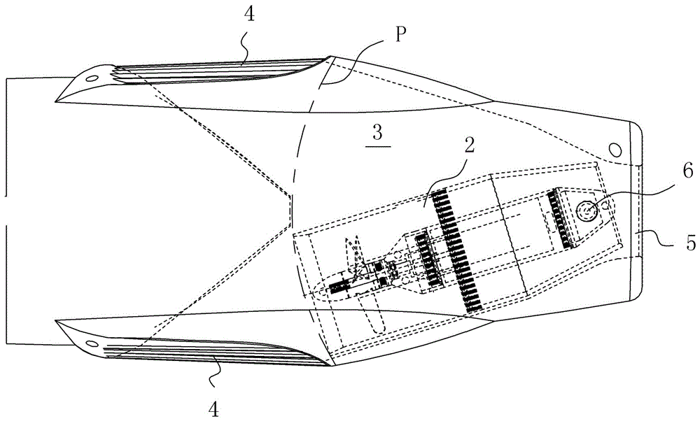
[0014] A thermal insulation power life buoy, comprising a life buoy body 1, the life buoy body is U-shaped, a heating device, a propeller 2 for providing power, a storage battery are installed on it, and a remote control for controlling the operation of the propeller, the remote control is controlled by a wireless signal Thrusters work.

[0015] In the heat-preserving power lifebuoy, the U-shaped bottom end of the lifebuoy body 1 is a round head; the plane that is balanced on the U-shaped paper surface is a horizontal plane, the direction perpendicular to the paper surface is a longitudinal direction, and the longitudinal center point of the lifebuoy body is located. The transverse plane is the transverse center plane, and the lifebuoy body 1 is arranged symmetrically along the transverse center plane; the diameter of the middle part of the U-shaped side of the lifebuoy body 1 is greater than the diameters at the two ends of the U-shaped si...


PUM


Abstract

The invention relates to a heat-preservation power life buoy. A life buoy body is in a U shape; a heating device, a propeller for providing power, and a remote controller for controlling the life buoy to move are arranged on the life buoy body; the life buoy body and an engine compartment on the life buoy body are arranged symmetrically; the propeller is rotatably arranged in the engine compartment. When a person fall into a river, a rescuer puts the life buoy body into water, and then controls the life buoy to move to a position where the person is located through the remote controller, so that the person who falls into the river can be quickly and conveniently rescued, and meanwhile, the temperature of the person who falls into the river can be recovered through the heating device of the life buoy; through the arrangement of the engine compartment and the propeller, any one face of the life buoy can be placed on water, so that the life buoy moves. With the use of the life buoy, the rescuing speed can be greatly improved, the person who falls into the river is protected, and the safety and the survival probability are improved.

Description

technical field [0001] The invention relates to a life buoy, in particular to a life buoy with a heat preservation function and a power system. Background technique [0002] The lifebuoy is a kind of water lifesaving equipment, usually made of foam plastic or other light materials with small specific gravity. The shape of the lifebuoy is ring-shaped, with an opening in the middle. The user puts his upper body through the middle opening and puts his hands on the ring-shaped lifebuoy, so that he can use the buoyancy of the lifebuoy to float on the water in a relaxed state. [0003] When someone accidentally falls into the water or rescues at sea, the rescuers need to sail to the vicinity of the person who fell into the water or the scene of the shipwreck, and then throw the lifebuoy to the side of the person who fell into the water. Also just have more abundant time and carry out rescue more safely. [0004] Existing lifebuoys all need to be thrown manually. On the one hand,...

Claims


Application Information

Patent Timeline
IPC IPC(8): B63C9/08B63H11/02
CPCB63C9/08B63H11/02B63H2011/004B63H2011/008
Inventor 鲁海森
Owner 珠海蓝创科技有限公司
Why Eureka
Try Eureka