
Fault diagnosis method for aero-engine control system sensor based on 3DCNN-JTFA

A technology for aero-engines and control systems, applied in general control systems, control/regulation systems, test/monitoring control systems, etc., and can solve problems such as data mismatches

Active Publication Date: 2020-06-09
NORTHWESTERN POLYTECHNICAL UNIV
View PDF10 Cites 13 Cited by
  • Summary
  • Abstract
  • Description
  • Claims
  • Application Information

AI Technical Summary

Problems solved by technology

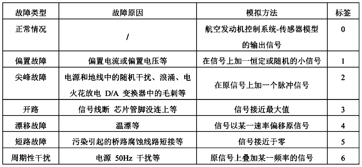
[0007] In order to avoid the deficiencies of the prior art, the present invention proposes a fault diagnosis method based on 3DCNN-JTFA for the sensor of the aero-engine control system. First, the mathematical model of the aero-engine-sensor is established, and a fault generator is designed to generate a large amount of fault data. , to solve the problem of data mismatch

Method used


Image

  • Fault diagnosis method for aero-engine control system sensor based on 3DCNN-JTFA
  • Fault diagnosis method for aero-engine control system sensor based on 3DCNN-JTFA
  • Fault diagnosis method for aero-engine control system sensor based on 3DCNN-JTFA

Examples


Embodiment Construction

[0070] Now in conjunction with embodiment, accompanying drawing, the present invention will be further described:

[0071] Embodiments of the present invention include the following steps:

[0072] Fault generator stage:

[0073] (1) The state variable model of the aeroengine is established by the component method, and the mathematical model of the aeroengine-sensor is established with the second-order inertial element as the mathematical model of the sensor;

[0074] The second order inertial elements are described as:

[0075]

[0076] Among them, ξ is the damping ratio of the sensor, w n is the natural frequency of the sensor, τ is the delay time;

[0077] The mathematical model of the aero-engine state variable is connected in series with the mathematical model of the sensor to form a mathematical model of the aero-engine control system;

[0078] (2) On the basis of the mathematical model of the aero-engine control system-sensor, through the analysis and simulation ...


PUM


Abstract

The invention relates to a fault diagnosis method for an aero-engine control system sensor based on 3DCNN-JTFA, and the method comprises the steps: building a fault generator on the basis of an aero-engine-sensor mathematic model; randomly mixing aircraft engine flight data with output signals of the fault generator to obtain a sample data set; processing the sample data set through a JTFA methodto obtain a time-frequency graph; performing label training on the sample data set according to the fault type to obtain a 3DCNN model; inputting real-time measurement data of an aero-engine control system sensor into a 3DCNN-JTFA model, and completing real-time fault detection and isolation through the steps of preprocessing, JTFA analysis to obtain a time-frequency diagram, label setting, 3DCNNclassification and the like. According to the invention, JTFA, 3DCNN and multiple binary classification technologies are combined, an offline learning and online operation mode is adopted, the methodis used in a diagnosis experiment, the method is not sensitive to noise interference, and the diagnosis efficiency is improved. Meanwhile, a fault generator is designed, so that the problem of data mismatching is solved.

Description

technical field [0001] The invention belongs to the field of fault diagnosis of aero-engine control system sensors, and relates to a method for fault diagnosis of aero-engine control system sensors based on 3DCNN-JTFA. Background technique [0002] Aeroengines are complex thermodynamic machines that work in high-speed, high-load, and high-temperature environments for a long time, and have extremely high requirements for reliability and safety. The aero-engine control system works on the basis of sensor measurement signals. However, due to the large amount of sensor measurement data, wide distribution, and special installation locations, it is the easiest control system to work in high temperature, high pressure, and strong vibration conditions for a long time. Failed parts. Once the sensor fails, it may lead to the failure of the entire control system, resulting in serious economic losses. Therefore, timely and effective fault diagnosis of sensors is of great significance ...

Claims


Application Information

Patent Timeline
Patent Type & Authority Applications(China)
IPC IPC(8): G06F30/20G06K9/62G06N3/04G06N3/08G05B23/02G01D18/00
CPCG06N3/08G05B23/0254G01D18/00G06N3/045G06F18/241
Inventor 李慧慧缑林峰杨江孙瑞谦
Owner NORTHWESTERN POLYTECHNICAL UNIV
Learn More