A precision manipulator handling system
A handling system and manipulator technology, applied in the field of bearing processing, can solve the problems of high labor intensity, high production cost, long processing cycle, etc., and achieve the effect of reducing labor intensity, saving use cost, and controlling precision and stability.
- Summary
- Abstract
- Description
- Claims
- Application Information
AI Technical Summary
Problems solved by technology
Method used
Image


Examples
Embodiment 1
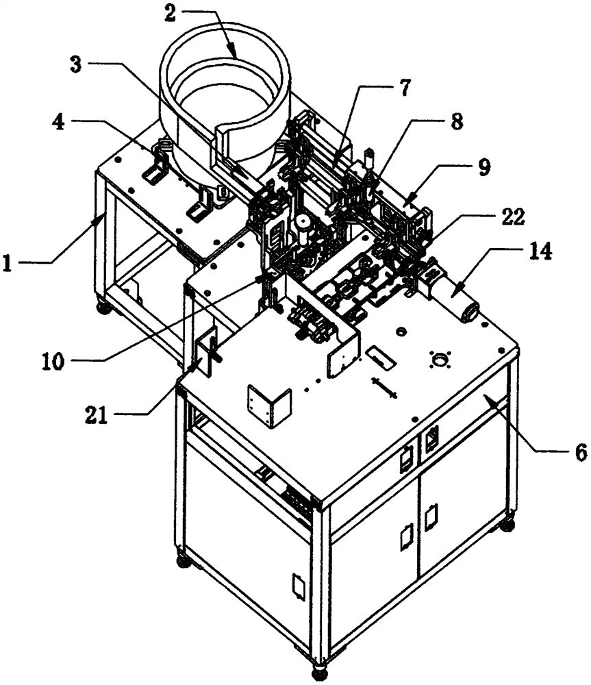
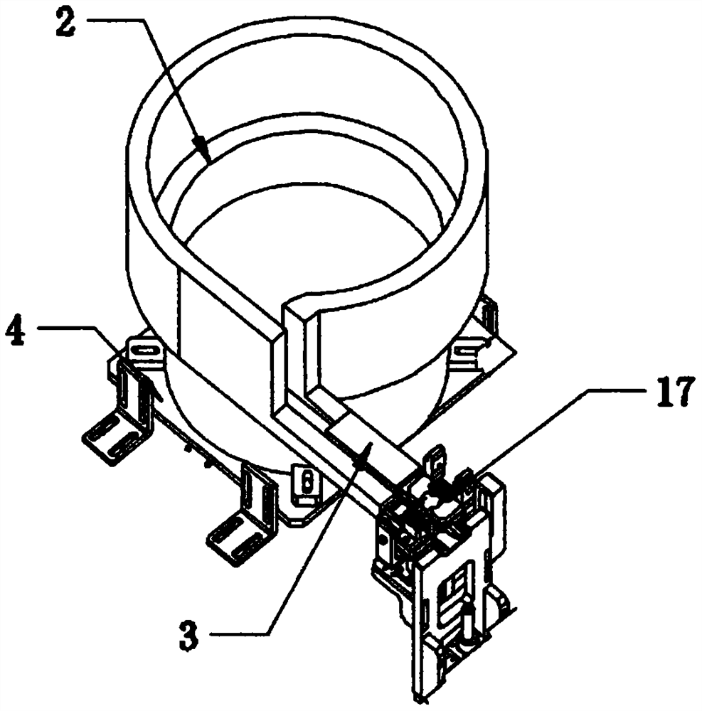
[0029] like Figure 1 to Figure 6 As shown, the automatic processing device for bearings according to a preferred embodiment of the present invention includes a bearing output mechanism, a gantry-type manipulator mechanism, a grease adding mechanism and a conveyor belt 22 . Wherein, the bearing output mechanism includes a feeding rack 1, a vibrating plate 2 and a feeding track 3, the middle part of the top surface of the feeding rack 1 is longitudinally fixed with a U-shaped limit plate 4, and the vibrating plate 2 is vertically fixed on the limit plate 4 In the middle part of the inner wall of the vibrating plate 2, an L-shaped material guide port 5 is provided on the side of the end away from the limit plate 4, and the feeding track 3 is fixed laterally on the side of the vibrating plate 2 on the side of the material guide port 5 through a tripod, and on the side of the feeding rack 1. An operation table 6 is fixedly arranged, and the gantry-type manipulator mechanism includ...
Embodiment 2
[0031] see Figure 1-6 , in the present invention, the feeding rack 1 is a hollow metal frame and the bottom surface is provided with a guide wheel 15 vertically movable through the corner code, and the bottom surface of the corner code on one side of the guide wheel 15 is fixedly provided with an adjustable foot 16; The frequency converter is controlled and driven by a built-in motor. The feeding track 3 on the side of the vibrating plate 2 is a concave metal power slide rail;
[0032]In a preferred embodiment, a control panel 18 is fixed laterally on the front side surface of one end of the console 6 away from the loading rack 1, and the control panel 18 communicates with the bearing output mechanism, the gantry-type manipulator mechanism, the grease adding mechanism and the conveying mechanism respectively through the controller. The driving motor 14 signal connection of the belt 22; the driving motor 14 is a frequency conversion type stepping motor, and the output shaft of...
Embodiment 3
[0036] see Figure 1-6 , the working principle of the automatic processing device of the bearing of a preferred embodiment of the present invention is: when in use, the bearing with processing is placed in the vibrating plate 2 and utilizes the control panel to regulate the rotation parameters of the vibrating plate 2, and the vibrating plate 2 and the feeding Under the joint action of the rails 3, the bearings are guided into the surface of the feeding rail 3 one by one by the material guide port 5 and the automatic feeding operation is completed by using the travel switch 17, and the pneumatic material moving plate 9 supporting the surface of the stand 7 above the operating table 6 is driven by compressed gas Move the material shifting manipulator 8 left and right to realize the fast and stable feeding of cyclic clamping and grease injection operations. Adjust the deflection angle of the turntable 11 through the adjustment lever to make it horizontal to facilitate the next op...
PUM
 Abstract
Description
Claims
Application Information
 - R&D
- Intellectual Property
- Life Sciences
- Materials
- Tech Scout
- Unparalleled Data Quality
- Higher Quality Content
- 60% Fewer Hallucinations
Browse by: Latest US Patents, China's latest patents, Technical Efficacy Thesaurus, Application Domain, Technology Topic, Popular Technical Reports.
© 2025 PatSnap. All rights reserved.Legal|Privacy policy|Modern Slavery Act Transparency Statement|Sitemap|About US| Contact US: help@patsnap.com