
Wing built-in aviation fuel tank pressurizing device

A pressurizing device and built-in technology, which is applied to the fuel tank of the power unit, the power unit of the aircraft, and the safety measures of the fuel tank, etc., can solve the problems of pressure jump, aircraft turbulence, fuel tank deformation, etc. Stabilizes and prevents oil backflow

Active Publication Date: 2020-06-05
王一涵
View PDF7 Cites 2 Cited by
  • Summary
  • Abstract
  • Description
  • Claims
  • Application Information

AI Technical Summary

Problems solved by technology

[0003] Existing pressurizing devices usually use air pumps or hydraulic cylinders to reduce the pressurization of the fuel tank. However, in the process of pressurization switching, it takes a certain amount of working time to increase the air pressure of the fuel tank. During the pressurization period , the insufficient fuel supply of the aircraft may easily cause problems such as turbulence of the aircraft. At the same time, the air pressure inside the fuel tank changes greatly, and the lack of buffer time may easily cause rapid jumps in pressure, which in turn may cause problems such as deformation of the fuel tank.
[0004] To this end, a wing built-in aviation fuel tank pressurization device is provided to solve the problem of stable pressurization of the fuel tank

Method used


Image

  • Wing built-in aviation fuel tank pressurizing device
  • Wing built-in aviation fuel tank pressurizing device
  • Wing built-in aviation fuel tank pressurizing device

Examples


Embodiment Construction

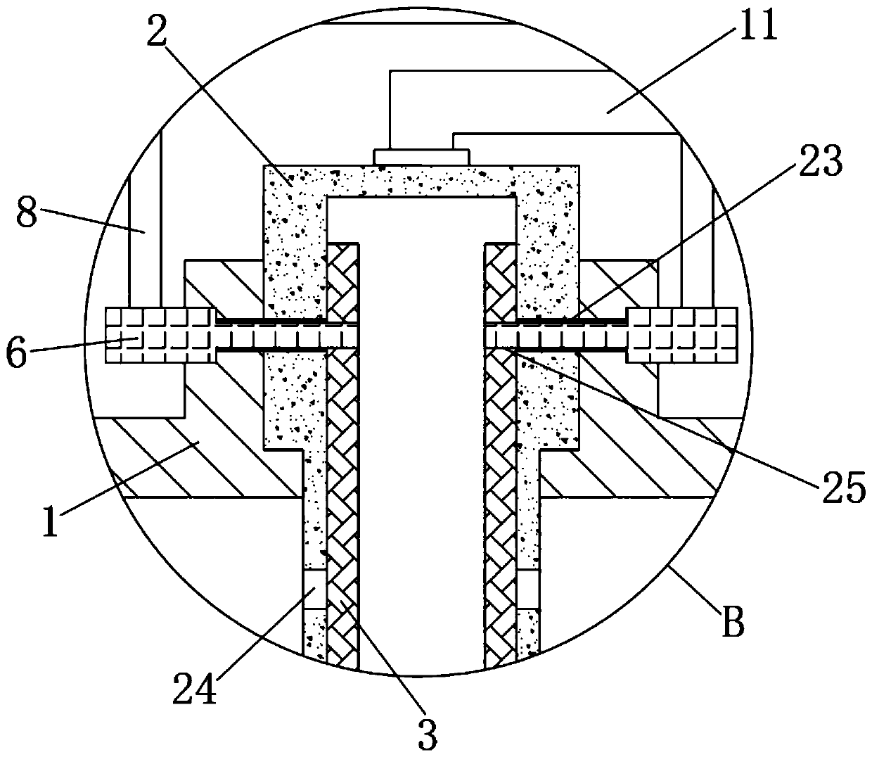
[0028] The following will clearly and completely describe the technical solutions in the embodiments of the present invention with reference to the accompanying drawings in the embodiments of the present invention. Obviously, the described embodiments are only some, not all, embodiments of the present invention. Based on the embodiments of the present invention, all other embodiments obtained by persons of ordinary skill in the art without making creative efforts belong to the protection scope of the present invention.

[0029] see Figure 1 to Figure 8 , the present invention provides a technical solution:

[0030] A wing built-in aviation fuel tank pressurization device, comprising an aviation fuel tank 1, the upper end of the aviation fuel tank 1 is plugged with a pressurized intubation tube 2, and the upper end of the pressurized intubation tube 2 is connected with an air intake pipe 11, the air intake pipe 11 The right side of the buffer tank 14 communicates with the buf...


PUM


Abstract

The invention relates to the technical field of aviation aircraft fuel tanks, in particular to a wing built-in aviation fuel tank pressurizing device. The device includes an aviation fuel tank, a pressurizing insertion pipe is inserted into an inner cavity at the upper end of the aviation fuel tank; a mounting bracket is vertically mounted on the outer edge of the upper end of the aviation fuel tank; symmetrical second rotating grooves are formed in the left arc side face and the right arc side face of the connecting position of an upper end boss of the aviation fuel tank and the pressurizinginsertion pipe. The device has the beneficial effects that through cooperation of the lower inserting pipe of the buffer box, on the premise of preventing oil from flowing back, buffering of air inletpressurization is achieved, and through cooperation with the throttling valve, the pressurization rate is effectively controlled; by arranging the lining pipe driven by the motor, communication between the second through hole and the third through hole is achieved, the process of needing rapid pressurization is achieved, the pressurization rate is increased, the buffer time needed by pressurization is shortened, and the airplane can run more stably.

Description

technical field [0001] The invention relates to the technical field of aviation fuel tanks, in particular to a wing built-in aviation fuel tank pressurization device. Background technique [0002] During the flight of the aircraft, due to the high altitude, the pressure is weak. In order to ensure the stable fuel supply in the wings of the aircraft, it is necessary to add a pressurization device in the fuel tank to make the oil supply stable and timely. [0003] Existing pressurizing devices usually use air pumps or hydraulic cylinders to reduce the pressurization of the fuel tank. However, in the process of pressurization switching, it takes a certain amount of working time to increase the air pressure of the fuel tank. During the pressurization period , Insufficient fuel supply to the aircraft can easily cause problems such as aircraft turbulence. At the same time, the air pressure inside the fuel tank changes greatly, and the lack of buffer time can easily cause rapid pre...

Claims


Application Information

Patent Timeline
Patent Type & Authority Applications(China)
IPC IPC(8): B64D37/00B64D37/10B64D37/32
CPCB64D37/005B64D37/10B64D37/32B64D2037/325
Inventor 陈志霖
Owner 王一涵
Learn More